Secondary ignition waveform
- Rukerin
-
 Topic Author
- Offline
- Junior Member
-

- Posts: 26
- Thank you received: 2
Please Log in or Create an account to join the conversation.
- Andy.MacFadyen
-

- Offline
- Moderator
-

- Posts: 3357
- Thank you received: 1037
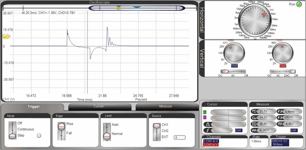
On a wasted spark system cylinders are paired as "companion cylinders" one cylinder getting a negative spark the other a conventional positive spark. If you put the probe on the companion cylinder to the one you hooked up to you will see a a wave form which is the right way up.
Also from the low spark voltage in your waveform it would appear it is actually a wasted spark which is of little use for diagnostics. Capturing a proper "useful" working spark is really a matter of setting the trigger level to capture only the higher voltage sparks. On the negatively fired plug lead on a wasted spark system all this is of couse turned upside down and the trigger level required is a high negative voltage.
If your scope has an option to invert the trace it will make this type of primary wave form much easier to understand.
" We're trying to plug a hole in the universe, what are you doing ?. "
(Walter Bishop Fringe TV show)
Please Log in or Create an account to join the conversation.
- Andy.MacFadyen
-
- Offline
- Moderator
-
- Posts: 3357
- Thank you received: 1037
lh3.googleusercontent.com/bf3kQfW3GnmF9Z...ESf9Q=w1920-h1080-no
Same waveform with explanation of some features
lh3.googleusercontent.com/azIgT4XBvah7Sb...yEbjA=w1920-h1080-no
" We're trying to plug a hole in the universe, what are you doing ?. "
(Walter Bishop Fringe TV show)
Please Log in or Create an account to join the conversation.
- Rukerin
-
Topic Author
- Offline
- Junior Member
-
- Posts: 26
- Thank you received: 2
Please Log in or Create an account to join the conversation.
- Andy.MacFadyen
-
- Offline
- Moderator
-
- Posts: 3357
- Thank you received: 1037
Ignition primary (and secondary) voltage waveforms should really be taken at the beginning of a throttle snap as this when the ignition is stressed most.
I don't see any controls on your scope to invert te waveform which is a pain but I have a couple inverted wave forms from different scopes.
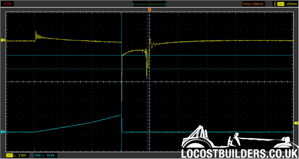
This is the inverted trace of the from the shared COP on another MG-Rover K16 EU3 engine taken on a Hantek 1008
Yellow trace is plug voltage
Blue trace is primary current.
Spark Burn Time on all these captures is around 0.9ms which is right for this model of engine, normally the range is 0.8 to sometimes over 2ms. Most engines have a similar pattern unless they have multi-spark ignition such as some Fords.
" We're trying to plug a hole in the universe, what are you doing ?. "
(Walter Bishop Fringe TV show)
Please Log in or Create an account to join the conversation.
- Andy.MacFadyen
-
- Offline
- Moderator
-
- Posts: 3357
- Thank you received: 1037
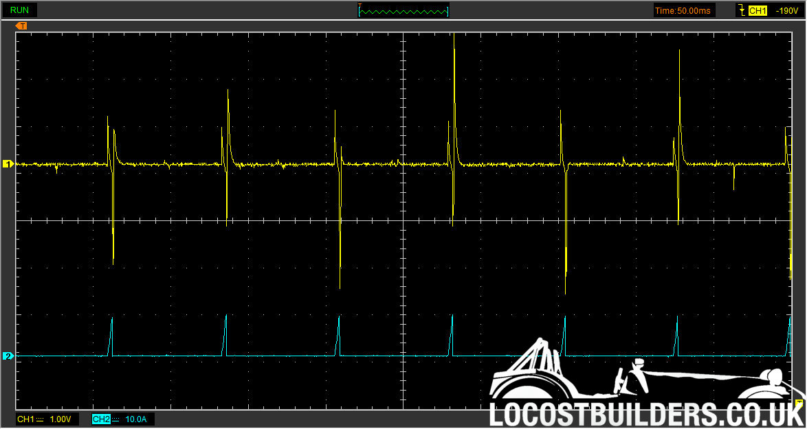
The working ignition sparks have the most negative voltage.
" We're trying to plug a hole in the universe, what are you doing ?. "
(Walter Bishop Fringe TV show)
Please Log in or Create an account to join the conversation.
- Andy.MacFadyen
-
- Offline
- Moderator
-
- Posts: 3357
- Thank you received: 1037
[img]http://locostbuilders.co.uk/upload/2016 - 1.jpg[/img]
Both the Hantek and DSO210 give surprisingly good results for very cheap hardware
" We're trying to plug a hole in the universe, what are you doing ?. "
(Walter Bishop Fringe TV show)
Please Log in or Create an account to join the conversation.
- Noah
-

- Offline
- Moderator
-
- Posts: 5051
- Thank you received: 1125
Please Log in or Create an account to join the conversation.
- Rukerin
-
Topic Author
- Offline
- Junior Member
-
- Posts: 26
- Thank you received: 2
Please Log in or Create an account to join the conversation.
- Andy.MacFadyen
-
- Offline
- Moderator
-
- Posts: 3357
- Thank you received: 1037
I have a busy day ahead but if I get time I will measure the resisstance of mine.
" We're trying to plug a hole in the universe, what are you doing ?. "
(Walter Bishop Fringe TV show)
Please Log in or Create an account to join the conversation.
- VizoEdward
-
- Offline
- New Member
-

- Posts: 13
- Thank you received: 1
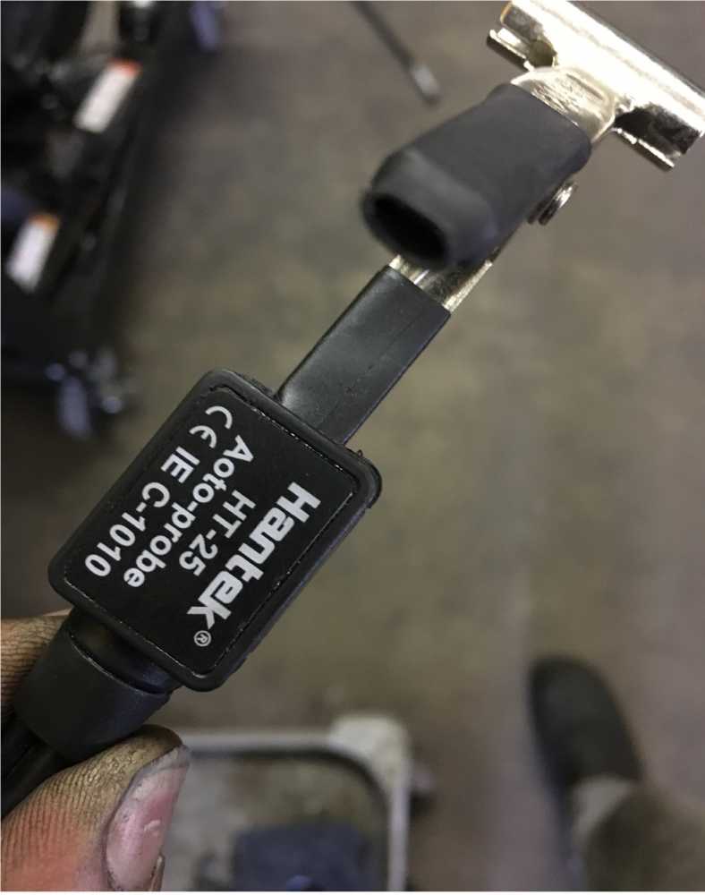
Would like to know if utilizing COP probes like pico pp357 or hantek ht25 need an attenuator conected to the scope?. (This probes are the ones that have a handle with an a paddle in the end to rest on the coil)
I tried utilize them for a very brief and scary moment on my Vantage Pro. I notice the color( yellow) of the trace at the high inductive spike part of the trace change to a white. Not good!. I double check that there was no high tension leakage anywhere at the set up. Although at that moment the Vantage survive I certainly would like to evaluate this procedure before I continue.
I have use a 20:1 attenuator while getting ignition/injection coil control waveforms in the same unit. No problems.
Additionally, have scoped secondary with the capacitive ignition cable set up ( high tension extension lead+ground clip) on the same unit. also, no mayor problems.
Although I can say that the trace I saw briefly using the probes(pico357/hantek25) DO indeed look a lot better compare with the ones captured with the capacitive cable set up.
But, my concern should be with the warning my scope is sending. I have assumed, before using the probes, that they must posses internals to cope with the high tension because I neither seen any warnings concerning the use of an attenuator or any other protection device.
I have try to contact the suppliers with not answers as yet. Definitely, something in the way I am utilizing the tool is guffy, like Mr. Danner mention sometimes on his videos.
If any one can give some light on the subject.............thanks for the hand.
Please Log in or Create an account to join the conversation.
- Andy.MacFadyen
-
- Offline
- Moderator
-
- Posts: 3357
- Thank you received: 1037
Not all scopes have a 20:1 scale as it is mainly for our type of work , but all the scopes I have used have a 10:1 I use a 10:1 attenuator quite often for injectors and solenoids.
ISTR some scopes (early Pico?) required a 30:1 attenuator when connected to ignition primaries.
" We're trying to plug a hole in the universe, what are you doing ?. "
(Walter Bishop Fringe TV show)
Please Log in or Create an account to join the conversation.
- VizoEdward
-
- Offline
- New Member
-
- Posts: 13
- Thank you received: 1
Yesterday received an answer from Pico Support Team, where they do mention that the probe pp357 does not need any other device to use with their own software or hardware. That is, aside from setting the scope on what probe(COP probe) the user is utilizing so it can adjust the trace- scale accordingly.
I am incline to say that my solution is a 500 or 1000 to 1 ratio attenuator with this probes in order to be safe. Since the conversion of the up to 40KV secondary circuit potential, brings the voltage to a 80V or 40 range that can be handled safely by the Vantage. But still at this moment a little unclear of this necessity on this probes. They should have the internal attenuation matched for their intend of usage.
Anyway, if any additional clarification or addition regarding this issue it will gladly appreciated. thanks
Please Log in or Create an account to join the conversation.
- matt.white
-
- Offline
- Elite Member
-

- Posts: 220
- Thank you received: 29
Please Log in or Create an account to join the conversation.
- VizoEdward
-
- Offline
- New Member
-
- Posts: 13
- Thank you received: 1
Remember I am using a Snap On scanner (VantagePro). As I read the scope specs sheet the maximum input voltage the unit support is +-200 DCV V. Certainly the screen is changing colors on me, from yellow at the beginning, from turn on,system voltage, up to the point on the firing line and part of the intermediate (coil oscillations) that the voltage trace seem to passe above the +-200V threshold that it is capable of handling, there at those moments the trace is definitely white. This is what I am most concern.
I believe, when you choose an attenuator is because your decision on what ratio to use is based on the expected max Voltage of the circuit you are connected to. For instance, coil primary control with max voltage up to 400. That voltage will go directly to the scope circuitry through the leads. To choose a ratio 20:1 would be reasonable.
That is why I believe COP ignition probes like picopp357 and Hantek HT25COP units must have internally attenuation ratio on 1000 unit to 1. But if this assumption is true, why my scope is flagging the situation? If everything was set right, the trace would be evenly colored all through out the screen. Yellow all the time, not yellow on some parts and white in others. So is it because the probes do not have the internal attenuation or there are not functioning right or an external attenuator should be used with the set up.
As, always eager to arrive to a clear understanding what is going on?. The input you guys bring to this issue is the best. Thanks for following up the discussion. Certainly I am eager to start utilizing well the probes that from what I seen so far, the trace details are much better that anything I have been able to capture with the tools/knowledge I have.
Thanks
Please Log in or Create an account to join the conversation.
- Andy.MacFadyen
-
- Offline
- Moderator
-
- Posts: 3357
- Thank you received: 1037
I got a couple of good captures. One of which turned up something unexpected.
" We're trying to plug a hole in the universe, what are you doing ?. "
(Walter Bishop Fringe TV show)
Please Log in or Create an account to join the conversation.
- Andy.MacFadyen
-
- Offline
- Moderator
-
- Posts: 3357
- Thank you received: 1037
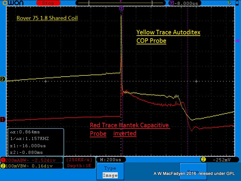
Red Trace Channel 1 Hantek Capcitive Plug Lead Probe --- inverted by scope.
Yellow Trace Channel 2 Autoditex COP Probe
" We're trying to plug a hole in the universe, what are you doing ?. "
(Walter Bishop Fringe TV show)
Please Log in or Create an account to join the conversation.
- Andy.MacFadyen
-
- Offline
- Moderator
-
- Posts: 3357
- Thank you received: 1037
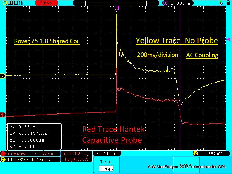
Yellow Trace Channel 2 --- No Probe No Physical Connection ! 200mv/div :dry:
" We're trying to plug a hole in the universe, what are you doing ?. "
(Walter Bishop Fringe TV show)
Please Log in or Create an account to join the conversation.
- Andy.MacFadyen
-
- Offline
- Moderator
-
- Posts: 3357
- Thank you received: 1037
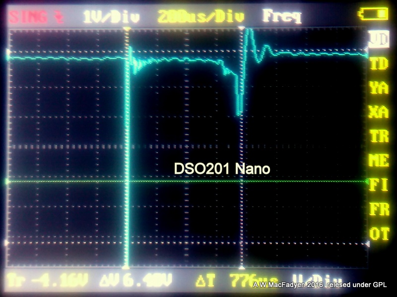
I have since tried it with DSO201 Nano and it also works nicely with that.
" We're trying to plug a hole in the universe, what are you doing ?. "
(Walter Bishop Fringe TV show)
Please Log in or Create an account to join the conversation.
- VizoEdward
-
- Offline
- New Member
-
- Posts: 13
- Thank you received: 1
In my case, I have utilize the Hantek HT25COP and Pico pp357(TA204). Neither of the two utilize a clamp around the HT wire, the probe is rested on top of the coil. These are the ones in question? Are this probes made to be used with out external attenuation devices placed in line with the sensing circuit.?. Or are they plug and go devices like the should be. In any case I have received notes from Pico and Snap On support Teams on the matter. Pico mention that their tool does not need nothing on their hardware/software units. Snap on goes about telling about the same. Most important I wanted to know why? my trace changes color, as I have previously mention on several post today. To Snap On it seem I have a problem with the screen set up.
Is the solution to this matter to try again with a different voltage scale? so it seem to Snap On. Simple. But the point is that I would like to have a little of more info before I risk the health of my dear scope. Which by the way is a Vantage Pro one that I got through a lot of effort and to damage it for ignorance will indeed be not a good thing. The biggest attenuator that I own is a 20:1, all with be easy if I had one 1,000 to 1 or even one(10K) like it is used on the capacitive clamp type. In that scenario will plug it, check result and most certainly that way answer every thing for me but I do not have it.
So again, if any light on the matter can be pointed this way. Thanks a lot
Please Log in or Create an account to join the conversation.