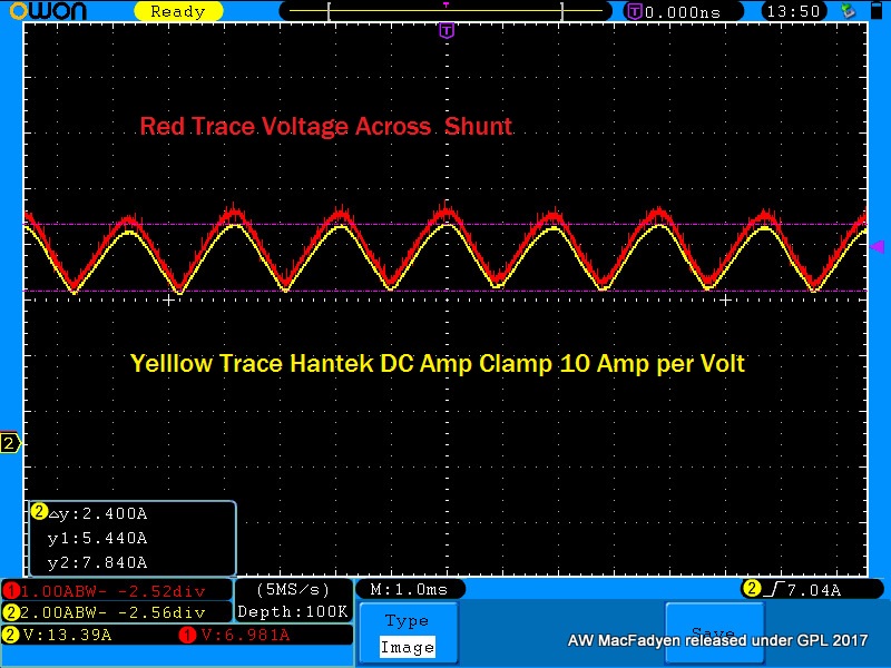
Fuel Pump Current Waveform without an Amp Clamp.
- Andy.MacFadyen
-
 Topic Author
- Offline
- Moderator
-

- Posts: 3357
- Thank you received: 1037
" We're trying to plug a hole in the universe, what are you doing ?. "
(Walter Bishop Fringe TV show)
Please Log in or Create an account to join the conversation.
- Andy.MacFadyen
-
Topic Author
- Offline
- Moderator
-
- Posts: 3357
- Thank you received: 1037
" We're trying to plug a hole in the universe, what are you doing ?. "
(Walter Bishop Fringe TV show)
Please Log in or Create an account to join the conversation.
- Tyler
-

- Offline
- Moderator
-
- Full time HACK since 2012
- Posts: 6129
- Thank you received: 1544
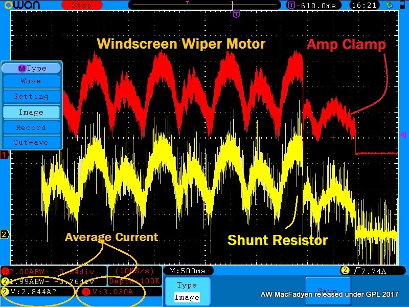
So how does the scaling work on the voltage trace? Is it possible to measure the overall current draw of the pump, or will this only show the commutator segments?
Please Log in or Create an account to join the conversation.
- Andy.MacFadyen
-
Topic Author
- Offline
- Moderator
-
- Posts: 3357
- Thank you received: 1037
The trick is getting a shunt resistor that hs low enough ressistance not to reduce the current flowing by any significant amount but still give a big enough voltage drop for the scope to read accurately and is a nice round number to make the maths easy. In theory the input resistance of the oscilloscope comes into the equation but in practice the imput resistance/impedance of a scope or DMM is so high it can be ignored.
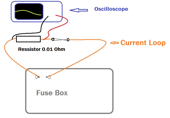
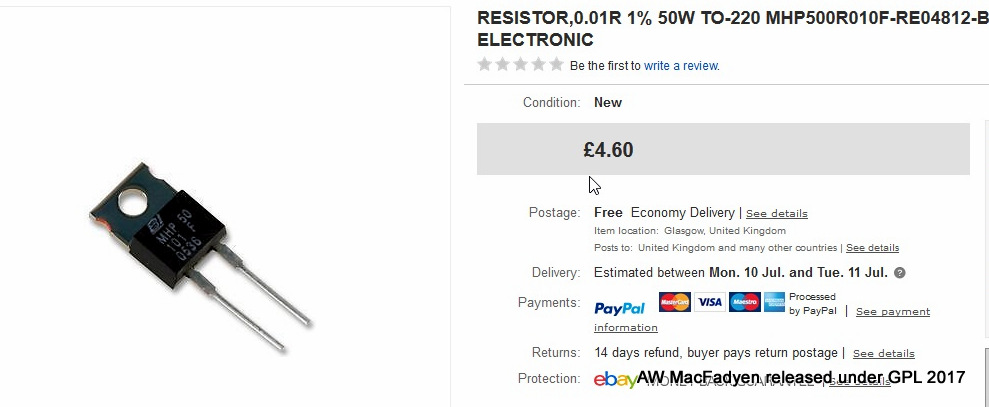
A good value for the shunt resistor is 0.01 Ohms
The volts drop across the shunt resistor is just V=IR so I=V/R
If for example the scope or voltmeter shows 100mV across the 0.01 ohm shunt resistor then
I=V/R = 0.100/0.01 = 10 amps current.
Which fits in the probe setting for amp clamps on many oscilloscopes.
One thing to watch is the channel ground wire will be floating around battery voltage so care has to be taken not to short it more so if the scope dosen't have the grounds for each channel isolated from each other.
It should work for other circuits, I tried it on the blower fan on my daily driver it showed nicely it was PWM controlled -- which I wasn'teven aware of! I see no reason why it shouldn't work on ignition coils and injectors.
" We're trying to plug a hole in the universe, what are you doing ?. "
(Walter Bishop Fringe TV show)
Please Log in or Create an account to join the conversation.
- Ro-longo
-

- Offline
- Elite Member
-

- North Salt Lake, Utah
- Posts: 168
- Thank you received: 43
"Silver bullets are for killing Werewolves, not fixing Cars." -Rob Longoria-
Please Log in or Create an account to join the conversation.
- Tyler
-
- Offline
- Moderator
-
- Full time HACK since 2012
- Posts: 6129
- Thank you received: 1544
It's probably important that the .01 ohm resistor is rated to carry the current of whatever circuit you've got it hooked to? :huh:
Please Log in or Create an account to join the conversation.
- Andy.MacFadyen
-
Topic Author
- Offline
- Moderator
-
- Posts: 3357
- Thank you received: 1037
The formula for the power power dissapated in the resistor is I squared R
A resistor with 10 Amps flowing through a 0.01 ohm resistor has to dissipate 1 Watt.
" We're trying to plug a hole in the universe, what are you doing ?. "
(Walter Bishop Fringe TV show)
Please Log in or Create an account to join the conversation.
- Andy.MacFadyen
-
Topic Author
- Offline
- Moderator
-
- Posts: 3357
- Thank you received: 1037
" We're trying to plug a hole in the universe, what are you doing ?. "
(Walter Bishop Fringe TV show)
Please Log in or Create an account to join the conversation.
- Andy.MacFadyen
-
Topic Author
- Offline
- Moderator
-
- Posts: 3357
- Thank you received: 1037
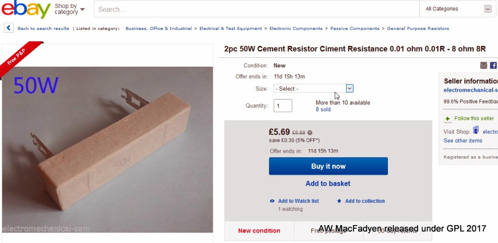
This type is probably easier to use.
" We're trying to plug a hole in the universe, what are you doing ?. "
(Walter Bishop Fringe TV show)
Please Log in or Create an account to join the conversation.
- Tyler
-
- Offline
- Moderator
-
- Full time HACK since 2012
- Posts: 6129
- Thank you received: 1544
Glad you mentioned that second type of resistor, 'cause I'm pretty sure that's the type my local Radio Shack is gonna have in stock. :lol:
Please Log in or Create an account to join the conversation.
- Andy.MacFadyen
-
Topic Author
- Offline
- Moderator
-
- Posts: 3357
- Thank you received: 1037
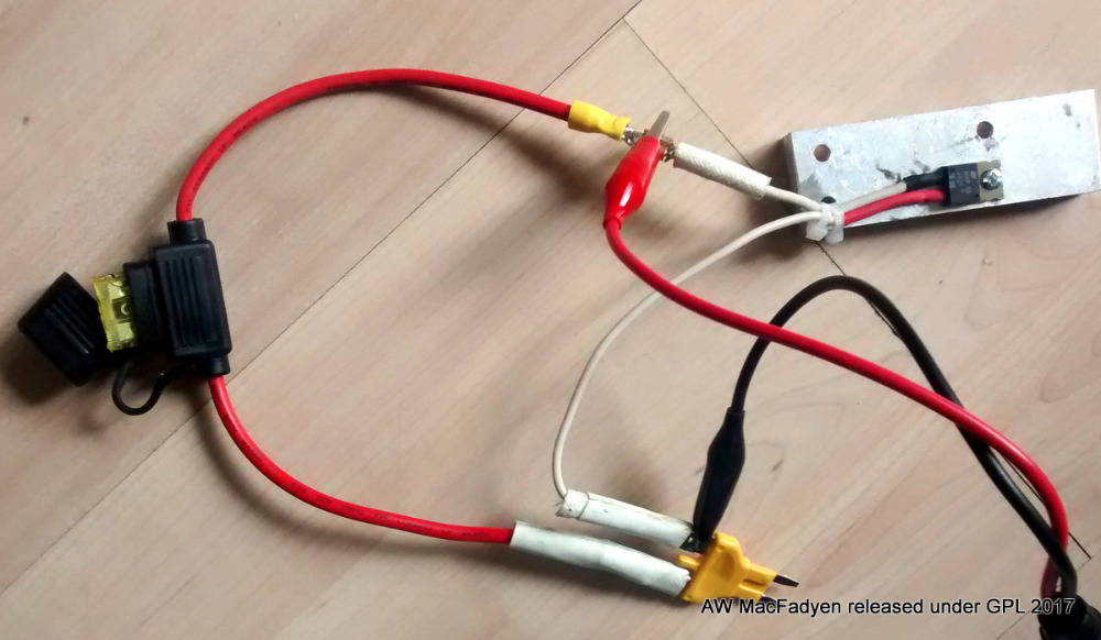
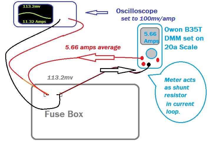
It occured to me that if only the current wave form was needed just hooking the oscilloscope leads up to show the voltage drop across the fuse would work so I tried it and it worked fine.
The second is problem with the original setup getting the current measurement scaled correctly Ohms law seems to be letting me down as to read current directly I need to set the scope's probe setting to 40 amp per Volt (25mV/Amp). My scope has this custom probe option I know most automotive scope don't.
I think the value of the resistor supplied might be wrong, the markings look correct as I have been over my Ohms law caculation a dozen times and checking a very low resistance with multimeter won't work.
" We're trying to plug a hole in the universe, what are you doing ?. "
(Walter Bishop Fringe TV show)
Please Log in or Create an account to join the conversation.
- Tyler
-
- Offline
- Moderator
-
- Full time HACK since 2012
- Posts: 6129
- Thank you received: 1544
Andy.MacFadyen wrote: A couple of developments on this, I had a free hour last night and ran a couple of tests.
It occured to me that if only the current wave form was needed just hooking the oscilloscope leads up to show the voltage drop across the fuse would work so I tried it and it worked fine.
I'm glad you mentioned this! 'Cause I was thinking about the waveforms I've seen on the scope while voltage dropping starter cables. There's always some kind of drop, and it usually looks exactly like a starter current waveform. Good thinking, sir.
Please Log in or Create an account to join the conversation.
- Andy.MacFadyen
-
Topic Author
- Offline
- Moderator
-
- Posts: 3357
- Thank you received: 1037
" We're trying to plug a hole in the universe, what are you doing ?. "
(Walter Bishop Fringe TV show)
Please Log in or Create an account to join the conversation.