Autoscope Technology, The Way to Perfection
- VladimirPostolovsky
-
 Topic Author
- Offline
- New Member
-

- Posts: 16
- Thank you received: 21
It was an elementary check of the ignition systems, checking the performance of various sensors, and diagnosing the condition of the engine mechanics.
In the workshop, I installed a large monitor, and everyone could watch the measurement process.
It was an air of mystery that we sometimes experience when visiting our doctor.
More than 25 years have passed.
With the help of an oscilloscope, tens of thousands of various cars brands were diagnosed.
Unique techniques were created that are used by automotive technicians in many countries of the world.
In 2005 I wrote my first article:
For example: The status of the engine mechanical condition can be diagnosed "by ear", "by smell", "by sight" - these are the most primitive methods, but with experience it is possible to determine with some probability the cause of trouble. It is possible to use different test equipment such as a compression tester, vacuum gauge and so on - this method is more precise, but it is more time consuming. However, we can combine all known diagnostics methods with computer technologies. As a result we can have modern methods of diagnostics, which needs minimal expense of time and efforts, but which give more precise results. Additionally we can learn more about the inner workings of the engine we are diagnosing.
In this article we examine the methods of computer diagnosis of the engine mechanical condition. The main point of this method is based on the following - with the help of special sensors and using the multi channeled digital oscilloscope on a PC we have the possibility to analyze the dynamic changes inside the engine, vacuum in the intake manifold, pressure in cylinders, pressure pulsation of the burnt gases in the exhaust system, pressure pulsation in the crank case, oil pressure pulsation in the lubrication system, starter current draw. Additionally we can synchronize a signal from the inductive sensor, placed on the high voltage wire of the first cylinder in the firing order on a gasoline engine or from the pressure transducer, installed on the high pressure injection line of the diesel engine first cylinder. In this manner we can perform a relative compression test quickly and accurately.
The suggested methods are completely universal and applicable for diagnostics of gasoline as well as diesel engine.
A waveform with a notch at the peak.

This type of testing will also isolate mechanical defects from electrical/electronic defects.
Please Log in or Create an account to join the conversation.
- VladimirPostolovsky
-
Topic Author
- Offline
- New Member
-
- Posts: 16
- Thank you received: 21
Perhaps many of you noticed how an experienced auto technician analyzes how the engine is working, bringing his hand to the exhaust pipe. The pulsation irregularity of the exhaust gases is felt even by hand and points out possible problems in the fuel injection system, ignition system, and also the engine mechanical condition. The pulsations of the exhaust gas pressure can yield information about the engine mechanical condition. For analyzing of the exhaust irregularity a vacuum actually pressure sensor is used, which is connected to the exhaust pipe.


If the decrease of pulsation level is observed and this deviation has a rhythmic character it means that one of the cylinders is working with decreased efficiency.

If comparing the results of this testing with the results of relative compression measurements it will be possible to say whether the engine mechanical or the engine control system is at fault.

Gases, leaking into the crankcase through a worn cylinder, causes there the pressure pulsations. Having measured the pulsation level of the crankcase gases with the help of the corresponding sensor, it is possible to judge about the state of the cylinders.
The pulsation waveform of the crankcase pressure of an idling engine in good condition.

On this waveform, a pressure pulse from one of the cylinders has a much higher amplitude than the others.

Please Log in or Create an account to join the conversation.
- VladimirPostolovsky
-
Topic Author
- Offline
- New Member
-
- Posts: 16
- Thank you received: 21
Observing the pressure waveform in a cylinder can give valuable diagnostic information.
However, a pressure transducer must be installed in the cylinder. - Usually installed in place of the spark plug.
The spark plug wire must be connected to a spark tester and ground. This is done to avoid damage to the ignition system or control systems.
The engine will work with the ignition in one cylinder disabled for 3-5 minutes. If possible, It is also preferable to disable fuel flow to the cylinder.
What information does the signal of this sensor carry?

The pressure crest in the cylinder waveform shows Top Dead Center (TDC) of piston movement. The second channel shows the signal from the inductive sensor connected to the coil wire or plug wire. This shows the exact moment of ignition. Knowing the engine Revolution Per Minute (RPM) and the time difference between the ignition pulse and TDC, it is possible to calculate a real ignition advance angle.
Analyzing the pressure waveform in the cylinder it is possible to measure the exact moment of valves opening and closing.


The moment of the exhaust valve closing.
The given testing gives the possibility to draw a conclusion about the work of gas distribution mechanism for each cylinder individually. Having the technical data of the tested engine (angles of valves opening and closing) it is possible to draw conclusions about the rate of wear of the camshaft cams.
In conclusion of this article I would like to add the following: None of the modern diagnostic devices will be able to make a correct diagnosis on its own. Diagnostic devices are just tools in the hands of the experienced technician.
Please Log in or Create an account to join the conversation.
- VladimirPostolovsky
-
Topic Author
- Offline
- New Member
-
- Posts: 16
- Thank you received: 21
Unfortunately it turned out to be a problem to find the good pressure sensor.
Most sensors do not meet measurement requirements.
Several dozen of sensors were tested.
Test result are given in this article:
The cylinder pressure sensor is used to obtain cylinder pressure waveforms.
The position of the characteristic points and sections of the cylinder pressure waveform of an internal combustion engine allows you to determine the relative position of the cam and crankshaft. The measurement and comparison of the absolute pressure in the cylinder at specific points on the waveform makes it possible to pass judgment on items such as cylinder leakage, compression ratio. Intake manifold flow conditions, exhaust system flow conditions, and valve timing.

The section below barometric pressure is likely to be the most important section for proper cylinder pressure analysis. For that reason, using pressure sensors calibrated for absolute measurement is important.
Absolute pressure sensor, whether they measure the pressure of atmospheric air, other gases, vapors, and/or liquids, are referenced to and measured from an absolute vacuum. One side of the sensor has a vacuum chamber. This chamber is implemented during the sensor manufacturing.
The pressure sensor may reach high temperatures during operation. It is important that the temperature drift of the sensor is minimal. If there is considerable temperature drift, the pressure readings and waveforms will change during the measurement.

For the purpose of this article, three types of pressure sensors from various manufacturers were tested for their ability to reproduce cylinder pressure waveforms during live conditions.

Px8, Px35, ADZ-SML-20.0 and Honeywell MLH300PAB01A.
The tests were performed with the engine at idle.
Test condition:
- engine temperature - 80 - 90 °C
- idle speed - 750 - 850 rpm
- fuel supply to test cylinder - disabled
- the ignition system for the test cylinder - disabled
- the test time does not exceed > 1 min

The pressure range of the ADZ-SML-20.0 sensor is -1…+16 Bar, which covers the entire pressure range in the diagnosed cylinder of gasoline engines.
As the sensor warms up, the waveforms shifts towards absolute vacuum.
Due to bias, the output voltage of the sensor does not match the measured pressure.

The waveform obtained when using the Honeywell MLH300PAB01A sensor is distorted in the form of a staircase (or stepped) signal.
This is because the Honeywell MLH300PAB01A series sensors are built using ASIC (Application Specific Integrated Circuit) technology, where the sensing element's output voltage is amplified and then converted by a built-in digital-to-analogue converter. Because of this, a stepped signal is formed at the output of the sensor, which loses its information content. There simply are not enough steps to faithfully reproduce the waveform.
The pressure range of the Honeywell MLH300PAB01A sensor is -1…+20 Bar, which covers the entire pressure range in the diagnosed cylinder of a gasoline engine.
As the sensor warms up, the waveform shifts towards the atmospheric pressure line.
Due to bias, the output voltage of the sensor does not match the measured pressure.

The range of the absolute pressure measured by the Px8 sensor allows to measure vacuum up to 0.85 Bar and pressure up to 6 Bar relative to the atmospheric pressure line (760 mm Hg). If the pressure in the cylinder exceeds 6 Bar, the top of the compression peak will be cut off or flattened. However, the available range is adequate in most all cases and the waveform fidelity is such that usable, detailed analysis of the rest of the waveform is possible.
Please Log in or Create an account to join the conversation.
- VladimirPostolovsky
-
Topic Author
- Offline
- New Member
-
- Posts: 16
- Thank you received: 21

The range of measured absolute pressure with the Px35 sensor allows measuring low pressure (vacuum) up to 0.85 Bar and high pressure up to 35 Bar relative to the atmospheric pressure line (760 mm Hg).
This range provides an opportunity to obtain reliable waveforms of the pressure in the cylinder of a gasoline engine.
This range allows you to determine most of the control points and make a correct assessment of the pressure curve in the cylinder of an internal combustion engine.
The Px8 and the Px35 series sensors provide measurement stability over the entire absolute pressure range and maintains high accuracy as it warms up.
Please Log in or Create an account to join the conversation.
- VladimirPostolovsky
-
Topic Author
- Offline
- New Member
-
- Posts: 16
- Thank you received: 21
Some time ago I received a WPS500X to test.

To check, I disassembled the WPS500 and saw that the measuring element is a Honeywell 19C500PA4K sensor.
This is a very good sensor.
It is the benchmark for comparative tests.
Specifications of Honeywell 19C500PA4K:
- Pressure Type: Absolute
- Operating Pressure: 500psi (35bar)
- Maximum pressure: 1200psi (82bar)
- Port Size: 1/8" (3.175mm) 27 NPT
- Output: 98 ~ 102mV, Proportional
- Supply voltage: 15V
- Termination Style: Cable with connector
- Operating temperature: -40°C ~ 125°C
- Package: Stainless steel
- Response time: 0.1ms
To compare the results, a Px35 sensor with a PxLonger extension from the USB Autoscope IV kit was simultaneously screwed into another engine cylinder (the piston of which moves synchronously with the piston of the tested cylinder, but the valve timing is shifted by 360°).

Reports comparison shows an unacceptably large discrepancy in test results. This leads to the conclusion that the use of the WPS500X pressure sensor with TA212 and M14 deep reach adapters does not allow obtaining a pressure graph in the cylinder, the accuracy of which will be acceptable for its subsequent analysis using the Px script.
Please Log in or Create an account to join the conversation.
- juergen.scholl
-

- Offline
- Platinum Member
-

- Active partschanger
- Posts: 1233
- Thank you received: 462
It has allowed me to find quickly and accurately the root cause in a great variety of diagnostics, over and over again.
One of its advantages is the ease of use through the automated scripts: they will allow even the not so experienced techn to evaluate the mechanical condition of an engine within minutes, analyze the complete charging/starting system in no time and so on.
Those who are interested in understanding (better) what really is going on in an ICE the sole study/analysis of a couple of oscilloscope capture will be a great learning experience, backed up by dynamic animations showing every single moment throughout the complete 720° engine cycle.
I love this fine piece of equipment.
An expert is someone who knows each time more on each time less, until he finally knows absolutely everything about absolutely nothing.
Please Log in or Create an account to join the conversation.
- VladimirPostolovsky
-
Topic Author
- Offline
- New Member
-
- Posts: 16
- Thank you received: 21
The position of the characteristic points and sections of the cylinder pressure graph of a gasoline internal combustion engine allows you to determine the relative position of the crankshaft and camshafts, measurement and comparison of the absolute pressure in the cylinder at some characteristic points of the graph allows you to determine the state of the seals of the diagnosed cylinder.
Based on this article, the Plug-In component "Phase measurement" was created in 2007.
This program made it possible to evaluate the operation of the engine in idling mode in real time.
PlugIn "Phase measurement" displayes the cylinder pressure waveform (the voltage waveform of the output signal of the pressure transducer in the cylinder) in a window of the program "USB Oscilloscope" when the engine at idle, marks the moments when the piston of the diagnosed cylinder is in the top/bottom dead centers (0°, 180°, 360°, 540°). Besides PlugIn highlights an admissible range for position of four characteristic points and sites of the waveform (D, E, I, L), which positions depend on mutual position crankshaft and camshafts.

Measurement of position of characteristic points and sites of the pressure waveform in the cylinder allows to judge correctness of mutual position crankshaft and camshafts.
Point 0°.
Position of the piston when it is on the most close distance from the cylinder head, name the Top Dead Center (TDC). The moment when the piston is in TDC and simultaneously intake and exhaust valves are closed, noted as 0°. The power stroke begins with this moment.
When the piston is in position TDC 0°, value of the pressure in the cylinder achieves the maximum. Sometimes this pressure name a dynamic compression.
Point D.
The exhaust valve of the petrol engine starts to open earlier, than the piston will achieve the bottom dead center. Thus the piston still goes away from the cylinder head and the volume between the piston and the cylinder head continues to increase, but absolute pressure in the cylinder starts to increase. Increasing of pressure in the cylinder occurs because the exhaust gases start to flow from the exhaust manifold into cylinder through the exhaust valve which opens. The point of the pressure waveform in the cylinder since which the exhaust gases start to flow into cylinder from the exhaust manifold, is noted by letter D.
It is possible to check correctness of mutual position of the exhaust camshaft and crankshaft of the petrol engine by position of point D.
If point D (the beginning of opening of the exhaust valve) is in range 130°…160° after TDC 0° (50°…20° before BDC 180°), the moment of the beginning of opening of the exhaust valve consider installed correctly.

PlugIn "Phase measurement" is highlighted the range 130°…160° after TDC 0° of the pressure waveform in the cylinder in a window of the program "USB Oscilloscope" and is noted by letter D.
Site E.
The flowing of gases from the exhaust manifold to the cylinder occurs because the absolute pressure in the exhaust manifold, approximately equals atmospheric pressure, is greater then the absolute pressure in the cylinder. The site of the pressure waveform in the cylinder where there is an flowing of the exhaust gases from the exhaust manifold to the cylinder, is noted by letter E.
It is possible to check correctness of mutual position of the exhaust camshaft and crankshaft of the petrol engine by position of the center of site E.
If the center of site E is in range 170°…195° after TDC 0° (-10°…+15° from BDC 180°), the moment of opening of the exhaust valve consider installed correctly.

PlugIn "Phase measurement" is highlighted the range 170°…195° after TDC 0° of the pressure waveform in the cylinder in a window of the program "USB Oscilloscope" and is noted by letter E.
Point 180°.
Position of the piston when the distance from it to the cylinder head is maximal, name the Bottom Dead Center (BDC). In BDC the piston stops, and changes the direction of movement to the opposite, started again to come to the cylinder head. The moment when the piston is in BDC and the intake valve is closed, and the exhaust valve is opened (or has started to open) is noted as 180°. Since this moment the piston starts "to push out" gases from the cylinder to the exhaust manifold.
Point 360°.
Achieved the second top dead center in the end of the exhaust stroke, the piston stops, and changes the direction of movement to the opposite, started again to goes away from the cylinder head. The moment when the piston is in the second TDC is noted as 360°. Since this moment the piston stops "to push out" gases from the cylinder to the exhaust manifold, and starts "to suck in" from an intake manifold the air/fuel mixture to the cylinder.
Site I.
When the piston has achieved point TDC 360° and has changed a direction of movement to the opposite, the exhaust valve is already almost closed. Owing to closing the channel connecting internal volume of the cylinder with the exhaust manifold, pressure inside the cylinder stops to equalizing with pressure in the exhaust manifold. The intake valve already has a slightly opened the channel of the air/fuel mixture and continues to open. Because the channel connecting internal volume of the cylinder with an intake manifold has started to open, pressure in the cylinder starts to equalizing with pressure in an intake manifold. As the value of absolute pressure in the cylinder is approximately equals atmospheric pressure, gases from the cylinder start to flow from the cylinder to the intake manifold, where pressure considerably below atmospheric.
The site of the pressure waveform in the cylinder where is the flowing of gases from the cylinder to the intake manifold is noted by letter I. By position of the center of site I it is possible to check correctness of mutual position of the intake camshaft and crankshaft of the petrol engine.
If the center of site I is in range 370°…390° after TDC 0° (±10° from the mark 380° after TDC 0°), the moment of opening of the intake valve consider installed correctly. On variable valve timed engines (equipped with the system VVT) the center of site I should be in range 380°…400° after TDC 0° (±10° from the mark 390° after TDC 0°).

PlugIn "Phase measurement" is highlighted the range 370°…390° after TDC 0° at the switched off option "VVT" on the PlugIn panel or a range 380°…400° after TDC 0° at the switched on option "VVT" (the option "VVT" should be switched on at variable valve timed engines). The range is noted by letter E.
Point 540°.
After achievement of the second bottom dead center the piston stops, and changes the direction of the movement to the opposite, started again to come nearer to the cylinder head. The moment when the piston is in BDC and the exhaust valve is closed, and the intake valve is opened (or has started to close) is noted as 540°. Since this moment the piston stops "to suck in" the air/fuel mixture from an intake manifold to the cylinder. But at high RPM filling of the cylinder by air/fuel mixture does not stop due to inertia of a stream of a mixture.
Point L.
The intake valve of the petrol engine closes a little after the moment of achievement by the piston of the second bottom dead center 540°. The pressure waveform in the cylinder in the area of closing of the intake valve is defined by a direction of movement of a mixture on the inlet channel directly ahead of the moment of closing of the intake valve.
At high RPM, before the moment of closing of the intake valve there is an effect of superfluous filling of the cylinder by the air/fuel mixture due to inertia of a stream of a mixture, and pressure in the cylinder starts to increase already from the moment of achievement by the piston of the bottom dead center 540°. With closing the intake valve, after a site concerning intensive increase of pressure in the cylinder there is an appreciable crisis of the waveform - since this moment velocity of increase of absolute pressure in the cylinder sharply decreases.
At low RPM appears the effect of the flowing of the mixture which has arrived earlier to the cylinder back to an intake manifold and as a consequence the pressure in the cylinder does not increase to the moment when intake valve does not close. With closing the intake valve, after flat site there is an appreciable crisis of the waveform - since this moment, absolute pressure in the cylinder starts to increase rather intensively.
The moment of closing of the intake valve is noted by letter L. Since this moment the piston starts to compress gases in the cylinder.
It is possible to check correctness of mutual position of the intake camshaft and crankshaft of the petrol engine by position of the point L.
If point L (the end of closing of the intake valve) is in range 560°…600° after TDC 0° (20°…60° after BDC 540°), the moment of the end of closing of the intake valve consider installed correctly.

PlugIn "Phase measurement" is highlighted the range 560°…600° after TDC 0° of the pressure waveform in the cylinder in a window of the program "USB Oscilloscope" and is noted by letter L.
Please Log in or Create an account to join the conversation.
- VladimirPostolovsky
-
Topic Author
- Offline
- New Member
-
- Posts: 16
- Thank you received: 21
This mistake very often confound even the most experienced technicians.
Sometimes it is necessary to disassemble engines to find the root cause of some misfires if relative compression and other tests done in the usual way do not give useful results.
Now, we have a way to "see" pressure changes inside the cylinders almost as soon as they happen, eliminating the need to disassemble the engines.
Here is a graph of cylinder pressure:

This signal was recorded on a gasoline engine, where a pressure transducer was installed instead of a spark plug.
Let's analyze this signal. Here we can easily find the TDC point.
But, that's probably all...
And this is how the process of the result of automatic analysis of the signal of the pressure transducer in the cylinder will look like:
Please Log in or Create an account to join the conversation.
- VladimirPostolovsky
-
Topic Author
- Offline
- New Member
-
- Posts: 16
- Thank you received: 21
Let's continue this topic.Misfire diagnosis is the problem we spend the most time on. Error P0301...
This mistake very often confound even the most experienced technicians.
Sometimes it is necessary to disassemble engines to find the root cause of some misfires if relative compression and other tests done in the usual way do not give useful results.
Now, we have a way to "see" pressure changes inside the cylinders almost as soon as they happen, eliminating the need to disassemble the engines.
I suggest watching the video:
Please Log in or Create an account to join the conversation.
- VladimirPostolovsky
-
Topic Author
- Offline
- New Member
-
- Posts: 16
- Thank you received: 21
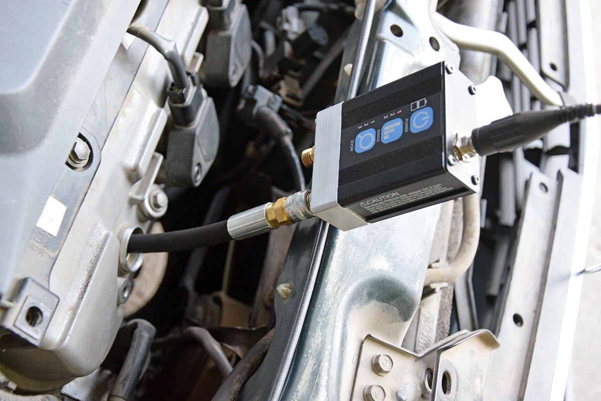
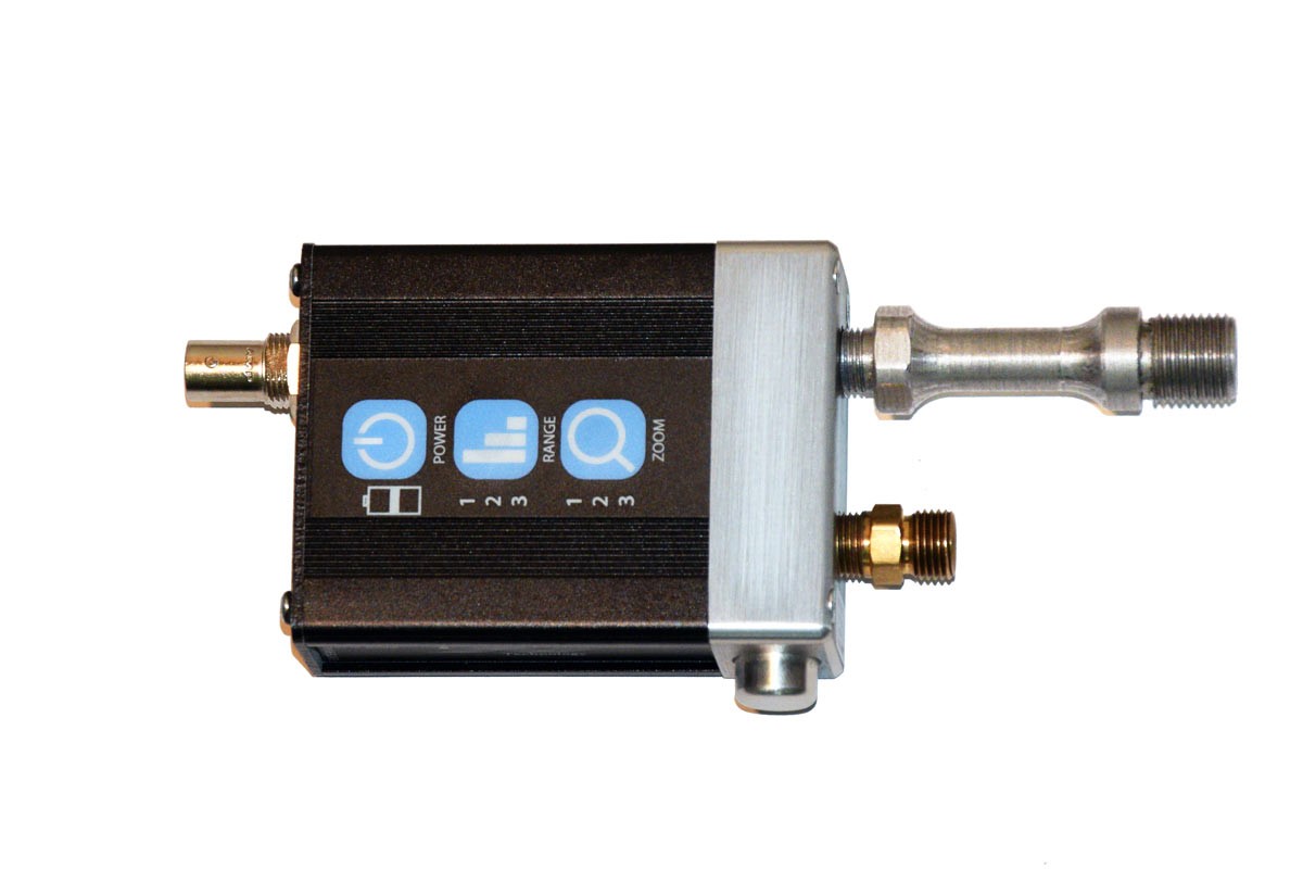
As a rule, many technicians are using T-junction adapters. On both sides, sensors are connected to the ends of the adapter.
Then this construction is connected to the cylinder being tested.
It is much more correct to check and compare the sensors on a car, where there are two spark plug holes per cylinder.
In this case, the sensors do not affect the readings among themselves.
The main thing is that the extension adapter is the same.
Also very important factor is the lack of quick release couplings on extension adapters. They introduce very large distortions in the waveform.
You can get more information in this video:
Please Log in or Create an account to join the conversation.
- sever.gonzalez
-
- Offline
- New Member
-
- Posts: 3
- Thank you received: 0
Please Log in or Create an account to join the conversation.
- VladimirPostolovsky
-
Topic Author
- Offline
- New Member
-
- Posts: 16
- Thank you received: 21
You can find the specifications here:
usbautoscope.eu/products/px35-pressure-transducer/#specs-2
Please Log in or Create an account to join the conversation.
- sever.gonzalez
-
- Offline
- New Member
-
- Posts: 3
- Thank you received: 0
Please Log in or Create an account to join the conversation.