A place to discuss hardware/software and diagnostic procedures
Adequately loading for VD testing
- philreed52
-
 Topic Author
- Offline
- New Member
-

Less
More
- Posts: 16
- Thank you received: 0
3 years 8 months ago #58782
by philreed52
Adequately loading for VD testing was created by philreed52
Hi all,
I’m looking for some advice on adequately loading a circuit to test voltage drop.
I worry that I may overload a delicate circuit or even under load a circuit and skew my results. Do you have any advice when it comes to bulb selection for the circuit you are testing when it is not easy to identify the usual current flow when in normal operation??
ie do you look at the wire size to gauge an idea of amperage?
Thanks in advance
Phil
Please Log in or Create an account to join the conversation.
- Paul P.
-

- Offline
- Platinum Member
-

Less
More
- Posts: 457
- Thank you received: 195
3 years 8 months ago #58790
by Paul P.
Never stop Learning.
Replied by Paul P. on topic Adequately loading for VD testing
I love my 9004 headlamp bulb, it draws 4 amps. Sometimes I'll use 4 of them to substitute a blower motor.
The idea is to match the substituted load current with what the circuit would normally draw.
However, car circuits are protected by fuses, so you could always use the fuse as a guide, ie: 20 amp fuse should be able to handle a 15 amp load.
I usually like to load up to 2/3 of the capacity of the fuse.
Otherwise, get your amp clamp out and start monitoring known working circuits and write it down for your own reference until you're familiar with them.
For sensor circuits, I'll use my meter, but for most else, it's bulbs, and let's hope they are bright, dim bulbs mean voltage drop.
Never stop Learning.
The following user(s) said Thank You: Noah
Please Log in or Create an account to join the conversation.
- philreed52
-
Topic Author
- Offline
- New Member
-
Less
More
- Posts: 16
- Thank you received: 0
3 years 8 months ago #58885
by philreed52
Replied by philreed52 on topic Adequately loading for VD testing
Thanks for your informative reply, good point about the fuses. I was concerned about loading sensor circuits where the polarity is reversed by a control module, ie a defroster flap motor that ive been scoping this morning. I think im more worried than i need to be but nobody wants to fry a computer lol
Please Log in or Create an account to join the conversation.
- Paul P.
-
- Offline
- Platinum Member
-
Less
More
- Posts: 457
- Thank you received: 195
3 years 7 months ago #58896
by Paul P.
An Input is a 'sensor' circuit. ie, MAP, MAF, TPS, etc. These can be tested for voltage drop. Here Paul Voltage drops sensor circuits.
A defroster flap motor is an OUTPUT. You can use a substituted load (bulbs) and bi-directionally control the circuit while measuring Voltage Drop on the wires. Or disconnect the controller and manually energize the load while monitoring the voltage drop.
There are many awesome videos of Paul testing Outputs in his Chapter 3 material.
Watching and learning from these videos will prevent you from 'frying' a module.
Never stop Learning.
Replied by Paul P. on topic Adequately loading for VD testing
loading sensor circuits where the polarity is reversed by a control module, ie a defroster flap motor
An Input is a 'sensor' circuit. ie, MAP, MAF, TPS, etc. These can be tested for voltage drop. Here Paul Voltage drops sensor circuits.
A defroster flap motor is an OUTPUT. You can use a substituted load (bulbs) and bi-directionally control the circuit while measuring Voltage Drop on the wires. Or disconnect the controller and manually energize the load while monitoring the voltage drop.
There are many awesome videos of Paul testing Outputs in his Chapter 3 material.
Watching and learning from these videos will prevent you from 'frying' a module.
Never stop Learning.
Please Log in or Create an account to join the conversation.
- Tyler
-

- Offline
- Moderator
-

- Full time HACK since 2012
Less
More
- Posts: 6129
- Thank you received: 1544
3 years 7 months ago #58902
by Tyler
Replied by Tyler on topic Adequately loading for VD testing
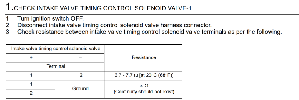
Weycraze is right on the money. Only other suggestion I can make is to use service information when possible. SI will sometimes provide you with a resistance range for a given component as part of a trouble tree. For example, Nissan has a specification for the intake camshaft solenoid on my Sentra:
Because I'm a lazy SOB, I put seven ohms into an Ohms Law calculator and got this:
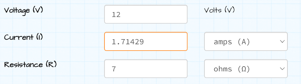
Now that you've got a rough current value for this solenoid, you can pick an appropriate substitute load.")
Because I'm a lazy SOB, I put seven ohms into an Ohms Law calculator and got this:
Now that you've got a rough current value for this solenoid, you can pick an appropriate substitute load.
The following user(s) said Thank You: Tutti57, Paul P.
Please Log in or Create an account to join the conversation.
Time to create page: 0.225 seconds