A place to discuss hardware/software and diagnostic procedures
Monitoring a ground using a scope
- trjp
-
 Topic Author
- Offline
- New Member
-

Less
More
- Posts: 16
- Thank you received: 2
3 years 10 months ago - 3 years 10 months ago #57934
by trjp
Monitoring a ground using a scope was created by trjp
I regularly use a scope to check voltages but I've encountered a couple of cases recently when I'd like to monitor presence/quality of a ground and I'm wondering how I should be doing this correctly?
Example 1
I suspect a sensor is losing it's ground (a controlled ground from a module rather than a rusty bolt) - what's the best way to show this on a scope??
Example 2
I have a coil-pack where the trigger wires are momentarily grounded - what's the best way of showing this/what should I be looking for in the data??(*)
(*) bearing-in-mind I see battery voltage on the trigger wires "through" the internal coil when not running/cranking anyway
Thanks!
Last edit: 3 years 10 months ago by Tyler.
Please Log in or Create an account to join the conversation.
- Ben
-
- Offline
- Platinum Member
-

Less
More
- Posts: 1098
- Thank you received: 215
3 years 10 months ago #57936
by Ben
Replied by Ben on topic Re:Module firmware updates with Forscan
There's multiple ways depending on which scope you have. Short answer assumes you have a shared ground across all channels and you hook your black ground scope lead to battery negative , you would then hook your positive scope lead to whatever you want to check ground of assuming it's something that carries current (coil,fuel pump,injector,etc)you will see the ground voltage. in the case of injectors and coils that are ground side fired you will see a voltage waveform as well (depending on Scope you may need an attenuator to do this without letting the magic smoke out as the flyback voltage from coils is easily in the 200v range and I typically see injectors around 50-100v)
Sent from my SM-G781V using Tapatalk
Sent from my SM-G781V using Tapatalk
The following user(s) said Thank You: Tyler
Please Log in or Create an account to join the conversation.
- trjp
-
Topic Author
- Offline
- New Member
-
Less
More
- Posts: 16
- Thank you received: 2
3 years 10 months ago #57953
by trjp
Replied by trjp on topic Re:Module firmware updates with Forscan
Thanks for that - I have something setup here, if I can't understand it I'll post the files and yell help again!
Please Log in or Create an account to join the conversation.
- Noah
-

- Offline
- Moderator
-

Less
More
- Posts: 5051
- Thank you received: 1125
3 years 10 months ago - 3 years 10 months ago #57963
by Noah
Replied by Noah on topic Monitoring a ground using a scope
*sorry it's kind of thrown together, trying to get this posted before I leave the shop.
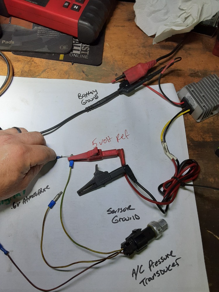
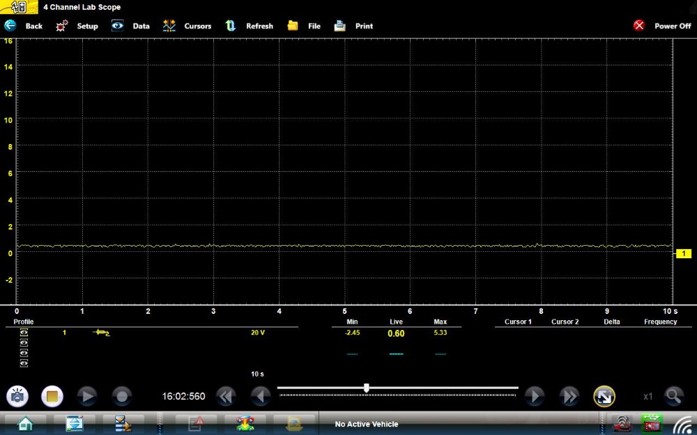
Here is an A/C pressure transducer circuit.
There's a 12v battery powering the 5v supply which powers the transducer. Scope is on battery negative, so just like it would be in the car.
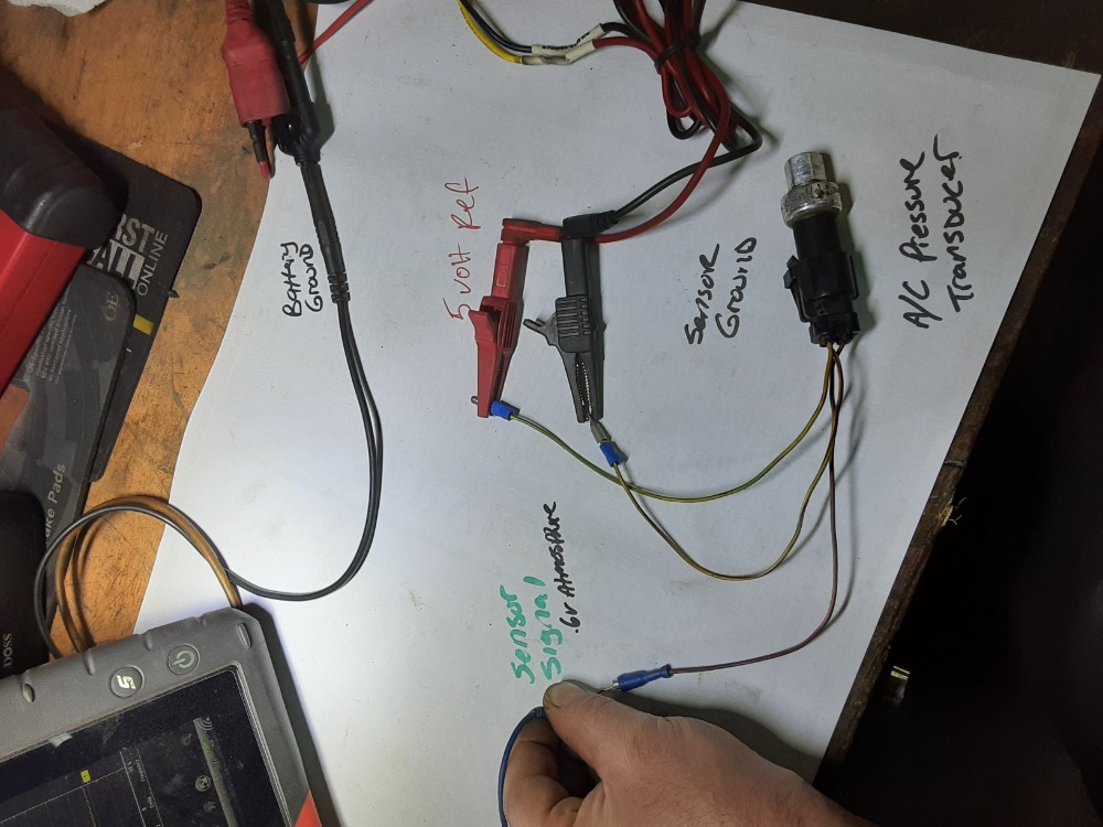
The sensor signal is 0.6v @ atmosphere.
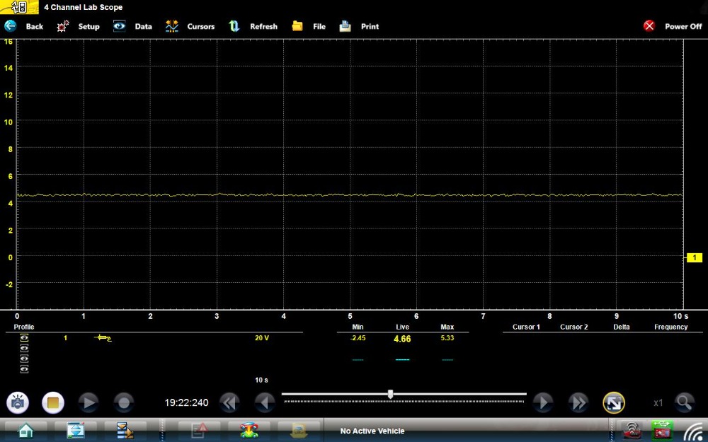
Next a bad ground is simulated
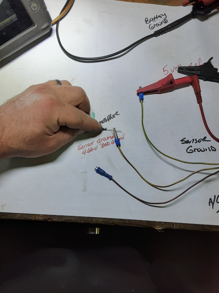
Sensor signal and sensor ground voltage are elevated to 4.66v each.
Here is an A/C pressure transducer circuit.
There's a 12v battery powering the 5v supply which powers the transducer. Scope is on battery negative, so just like it would be in the car.
The sensor signal is 0.6v @ atmosphere.
Next a bad ground is simulated
Sensor signal and sensor ground voltage are elevated to 4.66v each.
Last edit: 3 years 10 months ago by Noah.
The following user(s) said Thank You: Tyler, juergen.scholl, trjp
Please Log in or Create an account to join the conversation.
- trjp
-
Topic Author
- Offline
- New Member
-
Less
More
- Posts: 16
- Thank you received: 2
3 years 10 months ago #57977
by trjp
Replied by trjp on topic Monitoring a ground using a scope
That's very useful - thanks!
Please Log in or Create an account to join the conversation.
- trjp
-
Topic Author
- Offline
- New Member
-
Less
More
- Posts: 16
- Thank you received: 2
3 years 10 months ago #58180
by trjp
Replied by trjp on topic Monitoring a ground using a scope
When we measure a voltage with a multimeter or a scope, what we're actually measuring is the potential difference between 2 points in a circuit.
If you measure battery positive to battery negative you get battery voltage
If you measure module/sensor 5V reference to battery ground you should get 5V
If you measure between module ground and battery ground you SHOULD get 0v (or close to it)
They SHOULD be at the same potential because they should be connected together...
If your module ground is bad, you will see a potential difference (a voltage) - that's the sign of a bad ground
At least that's my take - I think that's how it works with a scope - I need to try it!!
Please Log in or Create an account to join the conversation.
- Andy.MacFadyen
-

- Offline
- Moderator
-
Less
More
- Posts: 3357
- Thank you received: 1037
3 years 9 months ago #58208
by Andy.MacFadyen
" We're trying to plug a hole in the universe, what are you doing ?. "
(Walter Bishop Fringe TV show)
Replied by Andy.MacFadyen on topic Monitoring a ground using a scope
The easiest way to understand monitoring grounds is to consider the main engine block to battery negative ground.
When the starter is operated the current through this connection is huge --- the continuous current can be 80 to 250 amps depending on the size of engine.
This cable has a ressistance on a good wire a with good connections the ressistance will be very low but with such a huge a current that big there will always be a noticeable difference in volatage between the cylinder block and the negative terminnal on the battery.
This can be measured by connecting the ground lead of the scope directly to the battery and the signal lead on the scope to a good ground on the block. With the scope channel on a 0 to 10v scale crank the engine and capture the voltage drop.
Anything below 0.2 volts is fine if it is above that you start looking for a bad connection or damaged cable.
" We're trying to plug a hole in the universe, what are you doing ?. "
(Walter Bishop Fringe TV show)
Please Log in or Create an account to join the conversation.
- juergen.scholl
-

- Offline
- Platinum Member
-
- Active partschanger
Less
More
- Posts: 1233
- Thank you received: 462
3 years 9 months ago #58214
by juergen.scholl
An expert is someone who knows each time more on each time less, until he finally knows absolutely everything about absolutely nothing.
Replied by juergen.scholl on topic Monitoring a ground using a scope
Connecting the scope in the way Andy just described is an excellent option to measure relative compression as well:
Just select a low voltage range like 0 to 500 mV total. The peaks will correspond to compression humps, no inversion needed or any amp clamp. Ocasionaly some filtering may get a clearer picture.
Just select a low voltage range like 0 to 500 mV total. The peaks will correspond to compression humps, no inversion needed or any amp clamp. Ocasionaly some filtering may get a clearer picture.
An expert is someone who knows each time more on each time less, until he finally knows absolutely everything about absolutely nothing.
Please Log in or Create an account to join the conversation.
Time to create page: 0.286 seconds