Question regarding switch input bypass test on power windows
- scopeman
-
 Topic Author
- Offline
- Senior Member
-

- Posts: 70
- Thank you received: 3
Now when i went to the drivers side master switch and tried to use my test light to put the window up/down nothing happened .Also when i put my DMM on the signal wire and ground i was reading 9.30v and when i pressed the switch for the window it dropped to about 4.50v .
The switch is controlled by the door module .Why was i not able to control the window with my testlight on the drivers side ..I thought if a module is controlling the switch then this test should work .Passenger side works fine ,there are no faults with the windows at all.The master switch has switches for windows for pass and drivers ,electric mirrors and lock/unlock .I was on the right wire when testing as i have the wiring diagram .Any help appreciated as i would like to understand why the test is not working on the drivers side.
Please Log in or Create an account to join the conversation.
- shootingchimp
-

- Offline
- New Member
-

- Posts: 8
- Thank you received: 4
The drivers side works in a similar fashion, except instead of dropping straight to ground. It uses resistors of different values which drops the signal down to varying voltages.
This allows the control unit to receive more signals using far fewer wires, as the drivers switch pack also has control for the other 3 doors.
So the reason your test didn't work was the module needs a specific voltage input signal, not a grounded input signal.
Hope this helps, Rob.
Please Log in or Create an account to join the conversation.
- scopeman
-
Topic Author
- Offline
- Senior Member
-
- Posts: 70
- Thank you received: 3
Thanks Rob.So how would i go about testing this switch correctly ? In section 2 paul says that if the switch goes to a module then we can bypass it with a test light and make the windows go up or down or lock and unlock the doors.This sounds like this is not the case here.This is so confusing as i was following the sections fine and understood the tests Paul shown now i try these out and they do not work.Paul if you read this would be nice to here your thoughts or better still if you have any videos explaining this then that would be great. Cheers Shaunshootingchimp wrote: The passenger side switches from normally open to closed, which drops the signal wire to ground.
The drivers side works in a similar fashion, except instead of dropping straight to ground. It uses resistors of different values which drops the signal down to varying voltages.
This allows the control unit to receive more signals using far fewer wires, as the drivers switch pack also has control for the other 3 doors.
So the reason your test didn't work was the module needs a specific voltage input signal, not a grounded input signal.
Hope this helps, Rob.
Please Log in or Create an account to join the conversation.
- shootingchimp
-
- Offline
- New Member
-
- Posts: 8
- Thank you received: 4
With these systems live data will show if the switch signals are being received at the bcm. Or testing with a scope on a 10s time base clearly shows the voltage steps as you operate the switch.
I would suggest you look at wiring diagram before deciding on any test method, if you are unfamiliar with the system.
Then you can apply the appropriate procedure, but more importantly know what results to expect.
Hope this helps, Rob.
Please Log in or Create an account to join the conversation.
- scopeman
-
Topic Author
- Offline
- Senior Member
-
- Posts: 70
- Thank you received: 3
Please Log in or Create an account to join the conversation.
- shootingchimp
-
- Offline
- New Member
-
- Posts: 8
- Thank you received: 4
This means I work on all makes and systems. Therefore I have learnt the hard way not to assume anything.
If I don't know or am unsure, I need to find out. Or I can very quickly dig a big hole for myself. If I base a diagnosis on flawed or missing information the consequences to my customer can be very expensive.
If you want more material try Advanced Automotive Fault Diagnosis by Tom Denton and Fundamental Electrical Troubleshooting by Dan Sullivan (also on youtube).
Or post on here and i'll do my best to answer.
Rob.
Please Log in or Create an account to join the conversation.
- scopeman
-
Topic Author
- Offline
- Senior Member
-
- Posts: 70
- Thank you received: 3
Please Log in or Create an account to join the conversation.
- Dylan
-

- Offline
- Moderator
-

- Belgium, Europe
- Posts: 1462
- Thank you received: 327
Please Log in or Create an account to join the conversation.
- Noah
-

- Offline
- Moderator
-
- Posts: 5051
- Thank you received: 1125
Please Log in or Create an account to join the conversation.
- ScannerDanner
-

- Offline
- Administrator
-

- Religion says do, Jesus says done!
- Posts: 975
- Thank you received: 500
scopeman wrote:
Thanks Rob.So how would i go about testing this switch correctly ? In section 2 paul says that if the switch goes to a module then we can bypass it with a test light and make the windows go up or down or lock and unlock the doors.This sounds like this is not the case here.This is so confusing as i was following the sections fine and understood the tests Paul shown now i try these out and they do not work.Paul if you read this would be nice to here your thoughts or better still if you have any videos explaining this then that would be great. Cheers Shaunshootingchimp wrote: The passenger side switches from normally open to closed, which drops the signal wire to ground.
The drivers side works in a similar fashion, except instead of dropping straight to ground. It uses resistors of different values which drops the signal down to varying voltages.
This allows the control unit to receive more signals using far fewer wires, as the drivers switch pack also has control for the other 3 doors.
So the reason your test didn't work was the module needs a specific voltage input signal, not a grounded input signal.
Hope this helps, Rob.
Rob is spot on with what he is telling you if the drivers side contains resistors of different values to drop the signal wire to specific levels. I would love for you to post the wiring diagram here so we can see it. Thanks!
Shaun, one other thing, there is no such thing as "always" and "never" in this field. I never claimed that bypass testing will work on every single system out there. I'm just teaching fundamentals. If you can see the resistors in that wiring diagram that Rob has mentioned, this was your red flag that the bypass test I mentioned in my Switch Inputs chapter would need to be modified to work. As he stated, there are specific voltages the module is looking for and your test light is not providing that.
There are other variables too. Like this GMC Acadia rear wiper/wash circuit. I had some issues with the bypass test on the one circuit because not only was it a switch input to a module, but the same circuit was used to energize the control side of a relay for the washer pump.
www.scannerdanner.com/scannerdanner-prem...LCJnbWMgYWNhZGlhIl0=
Don't be a parts changer!
Please Log in or Create an account to join the conversation.
- shootingchimp
-
- Offline
- New Member
-
- Posts: 8
- Thank you received: 4
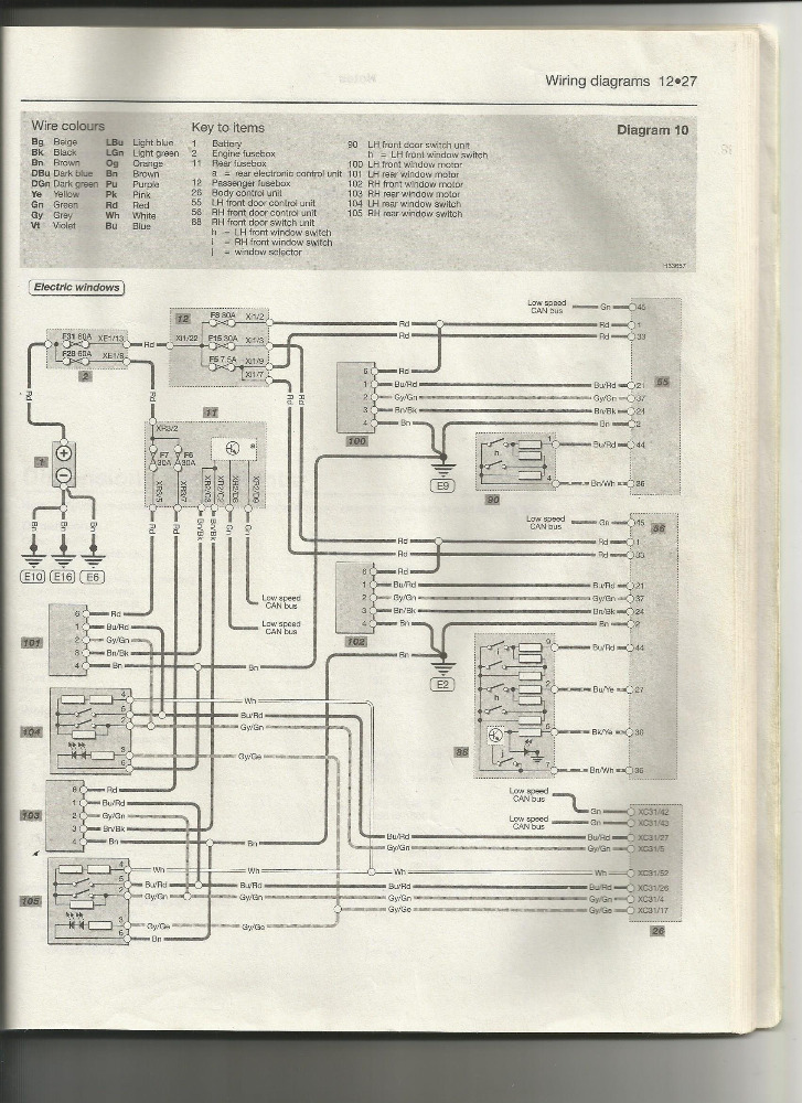
The this comes from a TIS supplier I use (Hella Gutman) which rewrites the original GM diagrams (which I also have but do not show the internal detail of the switches).
Because of this sometimes differences between left and right hand drive can be lost in translation (Hella Gutman based in Germany). If you use the key for the window switch locations you will see what i mean.
S21W should read power window switch FR (front right) or drivers door, as diagram is for a right hand drive vehicle.
The error is confirmed by the absence of a switch in the diagram key for the FR door existing !
Please Log in or Create an account to join the conversation.
- ScannerDanner
-
- Offline
- Administrator
-
- Religion says do, Jesus says done!
- Posts: 975
- Thank you received: 500
scopeman wrote: Now when i went to the drivers side master switch and tried to use my test light to put the window up/down nothing happened .Also when i put my DMM on the signal wire and ground i was reading 9.30v and when i pressed the switch for the window it dropped to about 4.50v .
.
Missed this part. This was another clue telling you that using a test light to substitute the switch was not going to work. Now if you used a variable resistor, you could have "dialed in" that specific resistance to drop the voltage to the 4.5v number that the switch was providing and that would have worked.
Don't be a parts changer!
Please Log in or Create an account to join the conversation.
- ScannerDanner
-
- Offline
- Administrator
-
- Religion says do, Jesus says done!
- Posts: 975
- Thank you received: 500
Don't be a parts changer!
Please Log in or Create an account to join the conversation.
- ScannerDanner
-
- Offline
- Administrator
-
- Religion says do, Jesus says done!
- Posts: 975
- Thank you received: 500
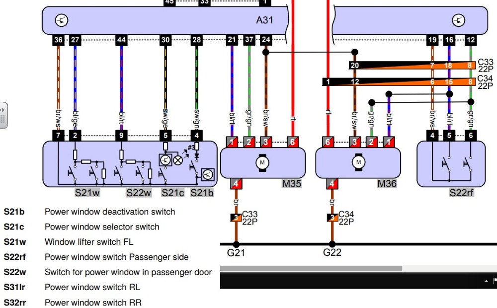
There is another variable here too. The drivers window switch in NOT just a master window switch. It is a module! Notice the transistor symbols in the diagram.
So now we are talking about "module to module" communication.
I would caution you in the future, if you are not 100% sure on circuit design to not perform any type of bypass test. I cannot give you an example on an input circuit where you could cause damage from an incorrect voltage level, as I've never seen it (on an input), but when it comes to module to module communication type stuff, you absolutely want to be extra cautious, just because.
Did the diagram you were using show the internals of the switch circuit?
Don't get me wrong my friend. Your questions are awesome! But you missed two red flags along the way. The first one was the voltage level of the circuit when you tested it's normal operation with the voltmeter (nice job on that btw) and then the second was the wiring diagram. And if your wiring diagram did not show you any internals like this one, then again, this is a red flag too because a lot of diagrams do NOT show the internals of a module. So the fact that the internals of this switch were not drawn is just as much of a red flag as if they were. Hope that makes sense.
Don't be a parts changer!
Please Log in or Create an account to join the conversation.
- scopeman
-
Topic Author
- Offline
- Senior Member
-
- Posts: 70
- Thank you received: 3
ScannerDanner wrote: Shaun,
There is another variable here too. The drivers window switch in NOT just a master window switch. It is a module! Notice the transistor symbols in the diagram.
So now we are talking about "module to module" communication.
I would caution you in the future, if you are not 100% sure on circuit design to not perform any type of bypass test. I cannot give you an example on an input circuit where you could cause damage from an incorrect voltage level, as I've never seen it (on an input), but when it comes to module to module communication type stuff, you absolutely want to be extra cautious, just because.
Did the diagram you were using show the internals of the switch circuit?
Don't get me wrong my friend. Your questions are awesome! But you missed two red flags along the way. The first one was the voltage level of the circuit when you tested it's normal operation with the voltmeter (nice job on that btw) and then the second was the wiring diagram. And if your wiring diagram did not show you any internals like this one, then again, this is a red flag too because a lot of diagrams do NOT show the internals of a module. So the fact that the internals of this switch were not drawn is just as much of a red flag as if they were. Hope that makes sense.
Hi Paul ,thanks for chiming in ..Yes my fault here for not understanding the design correctly . I guess i was not paying attention to the transistor in the master switch as i thought i'd be safe using the testlight. What threw me here Paul was i asked a question on your "How to test a power window switch/motor (1985-2001 Toyota) " last year as i was not sure on the test procedure which you explained and i understood after re watching it a few times on that particular circuit.What i did here is i misinterpreted what you said in one of the comments to me back then which was in the back of my mind when i was looking at this wiring diagram on this vehicle - here is the quote " Here is the key. If the switch is signalling a module, we can bypass it with a test light. If it is directly controlling the motor or load of a circuit we cannot."end of quote
Because i seen the switch in my diagram 88 in the picture go to the door control module 56 i thought i could use the test light method here as well to bypass the switch. I was assuming that the blu/red wire on pin 9 at the switch was signalling the module and this is where i made the mistake . This is why i did not understand the voltage readings on the drivers multi switch compared to when i first did the test on the passenger side that worked with the test light for some reason which i imagine by looking at the drivers side switch it does not show a transistor in it .Please don't think i was bashing any of your tests methods as i was merely trying to work out how this circuit was working and i got it wrong .
Please Log in or Create an account to join the conversation.
- ScannerDanner
-
- Offline
- Administrator
-
- Religion says do, Jesus says done!
- Posts: 975
- Thank you received: 500
Your diagram shows it too. There are three resistors in series, each one creating a specific voltage drop. This actually looks like a pull-down design, but the diagram is not conclusive. It could be a pull-up design too. The key would be knowing what pin 7 voltage level is. (on the diagram picture I posted, the br/ws wire).
If it is a ground then it is a pull-down. When switch 1 closes, there is one resistor before the signal wire goes to ground. When the second switch closes, there are two resistors in series before the signal wire goes to ground. Switch 1 would create a lower signal voltage then switch two would. So there are then two differen,t specific, input voltages the module is looking for to know what you just asked for. (auto up/down or manual I'm assuming)
Hope this makes sense.
And no problem on your questions! If you're not asking your not learning right?
Don't be a parts changer!
Please Log in or Create an account to join the conversation.
- scopeman
-
Topic Author
- Offline
- Senior Member
-
- Posts: 70
- Thank you received: 3
The brown and white wire on pin 7 of the drivers switch is a ground .I tested it with the dvom and loaded the circuit while watching my dvom to look at what each wire was doing before i even tried to use a test light to do a bypass test.If you look at my wiring diagram for the passenger side switch on the passenger door number 90 in my diagram it too shows the same resistors in that switch for the passenger door switch.If you look at the diagram Rob posted of the passenger side door switch S22rf it does not show any resistors in the switch.My diagram must be wrong for the passenger side switch on the passenger door as i was able to do a bypass test with the test light to ground .If my diagram was correct on the passenger side then i should not have been able to bypass the switch with my test light because of the resistors in there ?
If this is the case then i think this is what confused me when i was first testing how the circuit worked.My first test was on the passenger side switch on the passenger side door where i took some voltage measurements .I had my dvom black lead on ground and the red lead on the blu/red wire back probed at the switch connector .I was reading battery voltage on this wire.I hit the switch to load the circuit and it dropped to 0 volts.I then disconnected the switch and the voltage went to battery voltage.This then lead me to say it was a pull down circuit so i got my test light connected to ground and touched on the red/blu wire and the window went down.
Am i right in thinking that the reason i could bypass the passenger switch on the passenger door with my test light was because it does not have those resistors that are in my diagram 90 in the picture. Robs pic of the passenger side door switch s22rf does not show them there but does show the resistors in the drivers door switch on the drivers side door which i was not able to bypass like the passenger side ?
Please Log in or Create an account to join the conversation.
- scopeman
-
Topic Author
- Offline
- Senior Member
-
- Posts: 70
- Thank you received: 3
ScannerDanner wrote: Shaun
Your diagram shows it too. There are three resistors in series, each one creating a specific voltage drop. This actually looks like a pull-down design, but the diagram is not conclusive. It could be a pull-up design too. The key would be knowing what pin 7 voltage level is. (on the diagram picture I posted, the br/ws wire).
If it is a ground then it is a pull-down. When switch 1 closes, there is one resistor before the signal wire goes to ground. When the second switch closes, there are two resistors in series before the signal wire goes to ground. Switch 1 would create a lower signal voltage then switch two would. So there are then two differen,t specific, input voltages the module is looking for to know what you just asked for. (auto up/down or manual I'm assuming)
Hope this makes sense.
And no problem on your questions! If you're not asking your not learning right?
Just revisiting this as i am trying to understand series circuits and parallel circuits at the moment and this is one that threw me when i first looked at it..Paul says that when switch one closes there is one resistor before it goes to ground.Switch one would create a lower signal voltage than switch two would.Can someone explain why switch one would cause a lower voltage when closed than switch two which goes through two resistors.I thought that the voltage would be lower due to going through the two resistors when switch two is closed.?
Please Log in or Create an account to join the conversation.
- ScannerDanner
-
- Offline
- Administrator
-
- Religion says do, Jesus says done!
- Posts: 975
- Thank you received: 500
Don't be a parts changer!
Please Log in or Create an account to join the conversation.
- scopeman
-
Topic Author
- Offline
- Senior Member
-
- Posts: 70
- Thank you received: 3
Please Log in or Create an account to join the conversation.