[FIXED] 2000 Dodge Caravan, intermittent no crank with other electrical issues.
- bachi
-
 Topic Author
- Offline
- New Member
-

- Posts: 14
- Thank you received: 1
I have no DTCs, but it does appear I can communicate to the ECM and the symptoms are as followed:
Intermittent no crank - Occasionally the car does not crank, meaning I will turn the key to the crank position, and nothing happens (no relay click or anything) However, sometimes it does crank but doesn't start. Other times it does crank, and starts up and runs with no issues whatsoever.
Odometer flashing - When I remove the key, the odometer flashes randomly w/ no pattern, although not sure if this is related.
Unlock doesn't work - When I attempt to use the power locks for unlocking, nothing works (via the key and via the door switch). However, lock does appear to work from the key fob.
Lock stuttering - Sometimes the locks on the car stutter, as if someone was repeatedly pressing unlock/lock rapidly. This happened indefinitely in a loop (very consistent, not random) until I unplugged the battery. After re-plugging in the battery, the locks stop.
Brake light turns on - I don't know if this is normal operation, but the brake light comes on when I attempt to crank.
Relays clicking - After trying to start the car, sometimes I hear relays clicking, and it comes from the automatic shutdown relay.
Lastly, the alarm went off when I went to unlock the door with the key.
Please Log in or Create an account to join the conversation.
- Tyler
-

- Offline
- Moderator
-

- Full time HACK since 2012
- Posts: 6036
- Thank you received: 1515

I see that you have communication with the PCM, but do you have communication with during the no crank/no start? Or during the odometer flashing? Not trying to nitpick, but it matters.
The door lock symptoms would seem to have more to do with the BCM to me, but that's not to say it can't all be connected. My instinct is to follow the no crank first.
Speaking of, I have seen the original battery cable ends go bad on these vans. The crimp between the actual cable and the metal end get just a bit loose and develop resistance. When that happens, you end up with all kinds of weird symptoms. :silly: You can catch it by monitoring voltage drop from the block to the battery negative post (not the cable end) during cranking, when the load is at its highest. You can also use a thermal imager if available. The offending cable end will glow.
Please Log in or Create an account to join the conversation.
- bachi
-
Topic Author
- Offline
- New Member
-
- Posts: 14
- Thank you received: 1
I'll follow up after checking that and seeing if there is any significant voltage drop between the block and the battery negative post.
Edit: Not this Saturday, will follow up when I get a chance to look at the car again.
Please Log in or Create an account to join the conversation.
- bachi
-
Topic Author
- Offline
- New Member
-
- Posts: 14
- Thank you received: 1
I tried testing communication with the PCM during the no crank/ no start, but the moment I connect my scanner the car starts just fine...
When I unplug the scanner while the car is running, the car dies.
I have jumped the load side of the starter relay, and it will crank with no issue each time, so the starter circuit seems fine (whether or not the car actually starts up and runs depends on whether or not the other relays are clicking away).
With the other relays clicking away, I have unplugged a sensor and none of the wires gave me ground (all of them either gave me 5V or 12V). Does this mean that the PCM is not grounded properly?
Please Log in or Create an account to join the conversation.
- Tyler
-
- Offline
- Moderator
-
- Full time HACK since 2012
- Posts: 6036
- Thank you received: 1515
") There is definitely a ground problem. The symptoms go away with the scan tool connected because the tool bridges pin #4 and #5 at the DLC.
There is definitely a ground problem. The symptoms go away with the scan tool connected because the tool bridges pin #4 and #5 at the DLC.DLC pin #4 is chassic ground. #5 signal ground. One of them sucks.
") My money would be on #5.
My money would be on #5.Measuring voltage at DLC pins 4 and 5, scanner plugged in and unplugged, KOER, will tell you which direction to go in. Both pins should show zero volts under all conditions. One will show voltage with the scanner unplugged.
Please Log in or Create an account to join the conversation.
- bachi
-
Topic Author
- Offline
- New Member
-
- Posts: 14
- Thank you received: 1
I've noticed pin 5 at the DLC reads 0.81V, while pin 4 is pretty close to 0V (sometimes jumps to 0.01V)
I'm using a multimeter to measure these values.
Is 0.81V enough to cause an issue?
From here do you have any recommendations on where to start to trace down the issue (ie certain ground locations to check?)
Please Log in or Create an account to join the conversation.
- Nelson60
-
- Offline
- Junior Member
-

- Posts: 31
- Thank you received: 13
For exact locations, a subscription to Alldatadiy would be money well spent
Please Log in or Create an account to join the conversation.
- bachi
-
Topic Author
- Offline
- New Member
-
- Posts: 14
- Thank you received: 1
I've actually managed to find a wiring diagram, and so far it matches up so I'm fairly certain it's correct.
However, the wiring diagram seems to indicate that there is a direct ground from the PCM to battery negative, which has me a bit confused since the two connectors connecting directly to battery negative appear fine at first glance (The negative battery terminal has the main clamp, and also a little wire that connects to it, both are clean and have a solid connection to negative).
I'll follow up if I figure out anything tomorrow.
Please Log in or Create an account to join the conversation.
- Tyler
-
- Offline
- Moderator
-
- Full time HACK since 2012
- Posts: 6036
- Thank you received: 1515
bachi wrote: I've noticed pin 5 at the DLC reads 0.81V, while pin 4 is pretty close to 0V (sometimes jumps to 0.01V)
I'm using a multimeter to measure these values.
Is 0.81V enough to cause an issue?
Under what conditions was that reading taken? KOEO, scan tool unplugged?
For our reference, what's the 8th digit of the VIN?
However, the wiring diagram seems to indicate that there is a direct ground from the PCM to battery negative, which has me a bit confused since the two connectors connecting directly to battery negative appear fine at first glance (The negative battery terminal has the main clamp, and also a little wire that connects to it, both are clean and have a solid connection to negative).
Try watching voltage at DLC pin #5 with your DMM connected to the B- *POST* while wiggling the negative cable end and the cable near the end crimp. KOEO, no scan tool connected. Turn the headlights on for some extra load. If the voltage starts fluctuating, you're in the right area.
Please Log in or Create an account to join the conversation.
- Matt T
-
- Offline
- Platinum Member
-

- Posts: 751
- Thank you received: 276
bachi wrote: I've actually managed to find a wiring diagram, and so far it matches up so I'm fairly certain it's correct.
Is this wiring diagram factory or aftermarket? Aftermarket sometimes leave things like splice packs out to make the diagrams easier to read. The PCM only having one ground ran straight to B- doesn't sound right.
Please Log in or Create an account to join the conversation.
- bachi
-
Topic Author
- Offline
- New Member
-
- Posts: 14
- Thank you received: 1
Key out = 0.83V
Key in, off = 0.84V
Key in, accessory = 1.16 to 1.58 (jumps around, relays clicking)
key in, on = 5.1 to 5.3 (jumps around, relays clicking)
key in, start (attempting to crank, but no crank) = 6V and rising
The 8th digit of the VIN is R
Watching voltage at pin 5, headlights on, DMM connected to B post, key out, no scan tool connected, while wiggling the negative post, the voltage remains at a constant 0.84V.
Seems that the voltage fluctuates greatly when the key is either on or in accessory.
Please Log in or Create an account to join the conversation.
- bachi
-
Topic Author
- Offline
- New Member
-
- Posts: 14
- Thank you received: 1
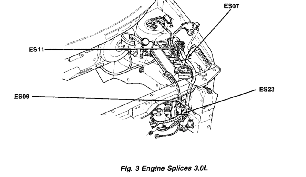
There is a mention of engine splice 11 (ES11) grounding the PCM, but I can't find that splice connecting to the body of the car; from the diagram I just see it splicing to other components and grounding directly to the negative of the battery.
Please Log in or Create an account to join the conversation.
- Matt T
-
- Offline
- Platinum Member
-
- Posts: 751
- Thank you received: 276
bachi wrote: There is a mention of engine splice 11 (ES11) grounding the PCM, but I can't find that splice connecting to the body of the car; from the diagram I just see it splicing to other components and grounding directly to the negative of the battery.
It may connect to the engine rather than the body. And based on those voltage readings you just posted it sounds like you've got a bad engine ground. Repeat your voltage checks with the red lead on the engine and black on B- terminal.
Please Log in or Create an account to join the conversation.
- Tyler
-
- Offline
- Moderator
-
- Full time HACK since 2012
- Posts: 6036
- Thank you received: 1515
bachi wrote: My bad I should have taken values at differents states, here's what I found:
Key out = 0.83V
Key in, off = 0.84V
Key in, accessory = 1.16 to 1.58 (jumps around, relays clicking)
key in, on = 5.1 to 5.3 (jumps around, relays clicking)
key in, start (attempting to crank, but no crank) = 6V and rising
No worries. Nice readings.
The 8th digit of the VIN is R
Thanks, sir!
Watching voltage at pin 5, headlights on, DMM connected to B post, key out, no scan tool connected, while wiggling the negative post, the voltage remains at a constant 0.84V.
Ah well, worth a try. :silly:
Seems that the voltage fluctuates greatly when the key is either on or in accessory.
I believe that's because you're increasing the electrical load, and thus the voltage drop. Here's the wiring diagram for anyone following along:

And this is what we get when trying to track down ES11:
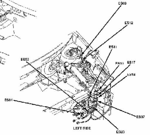
'Bout as clear as mud. :silly: In my experience, splice packs rarely fail unless there's been a collision. I'd say you're voltage drop is most likely between ES11 and the battery.
That small cable at the B- cable end that you mentioned earlier? I bet that's the wire you're chasing. I know it's tight and looks clean, but that doesn't mean there can't be voltage drop taking place.
Please Log in or Create an account to join the conversation.
- bachi
-
Topic Author
- Offline
- New Member
-
- Posts: 14
- Thank you received: 1
Is there any way to tell which one is correct?
I've taken out the battery and the battery tray to take a look; Nothing seems out of place yet but I have yet to take measurements. What do you recommend I do at this point? Should I put the battery back in, cut at ES11 to try to take voltage drops between it and the little wire at the negative terminal?
Also thanks for the contributions from everyone, they are all really helpful
")
Please Log in or Create an account to join the conversation.
- bachi
-
Topic Author
- Offline
- New Member
-
- Posts: 14
- Thank you received: 1
Matt T wrote:
bachi wrote: There is a mention of engine splice 11 (ES11) grounding the PCM, but I can't find that splice connecting to the body of the car; from the diagram I just see it splicing to other components and grounding directly to the negative of the battery.
It may connect to the engine rather than the body. And based on those voltage readings you just posted it sounds like you've got a bad engine ground. Repeat your voltage checks with the red lead on the engine and black on B- terminal.
I could try this, would just have to put everything back together.
Hmm, given that the starter runs every time I jump the load side of the relay, do you still think it could be a bad engine ground?
Please Log in or Create an account to join the conversation.
- Tyler
-
- Offline
- Moderator
-
- Full time HACK since 2012
- Posts: 6036
- Thank you received: 1515
bachi wrote: I've taken out the battery and the battery tray to take a look; Nothing seems out of place yet but I have yet to take measurements. What do you recommend I do at this point? Should I put the battery back in, cut at ES11 to try to take voltage drops between it and the little wire at the negative terminal?
Also thanks for the contributions from everyone, they are all really helpful
If it were my van, I'd be very tempted to run a new wire from as close to ES11 as I can reasonably get. :lol: But correctly, yes, you should track down ES11 and voltage drop further to track down the exact failure.
I love having the failure in my hand as much as the next tech. But it's Saturday and tracking down splice packs really sucks. :silly:
Please Log in or Create an account to join the conversation.
- Matt T
-
- Offline
- Platinum Member
-
- Posts: 751
- Thank you received: 276
bachi wrote: Hmm, given that the starter runs every time I jump the load side of the relay, do you still think it could be a bad engine ground?
Missed that part. Engine ground should be OK if it cranks.
Looking at that wiring diagram Tyler posted ES11 is going to be, at least somewhat, intact if it can provide an alternate PCM ground thru' the DLC.
Please Log in or Create an account to join the conversation.
- bachi
-
Topic Author
- Offline
- New Member
-
- Posts: 14
- Thank you received: 1
With the key in the on position (engine not running), scan tool unplugged
The voltage at pin 5 does read 5V, but it slowly creeps up and hits 7.9V (takes roughly 6 mins for it to do so)
Please Log in or Create an account to join the conversation.
- Tyler
-
- Offline
- Moderator
-
- Full time HACK since 2012
- Posts: 6036
- Thank you received: 1515
bachi wrote: One thing I did notice:
With the key in the on position (engine not running), scan tool unplugged
The voltage at pin 5 does read 5V, but it slowly creeps up and hits 7.9V (takes roughly 6 mins for it to do so)
IMO, that's the high resistance in the ground circuit heating up with current flow.
Please Log in or Create an account to join the conversation.