2009 Nissan Frontier Intermittent A/C on 2 and 3 speed fan setting
- forumjoe
-
 Topic Author
- Offline
- Junior Member
-

- Posts: 26
- Thank you received: 1
Thanks Matt,
joe
Please Log in or Create an account to join the conversation.
- forumjoe
-
Topic Author
- Offline
- Junior Member
-
- Posts: 26
- Thank you received: 1
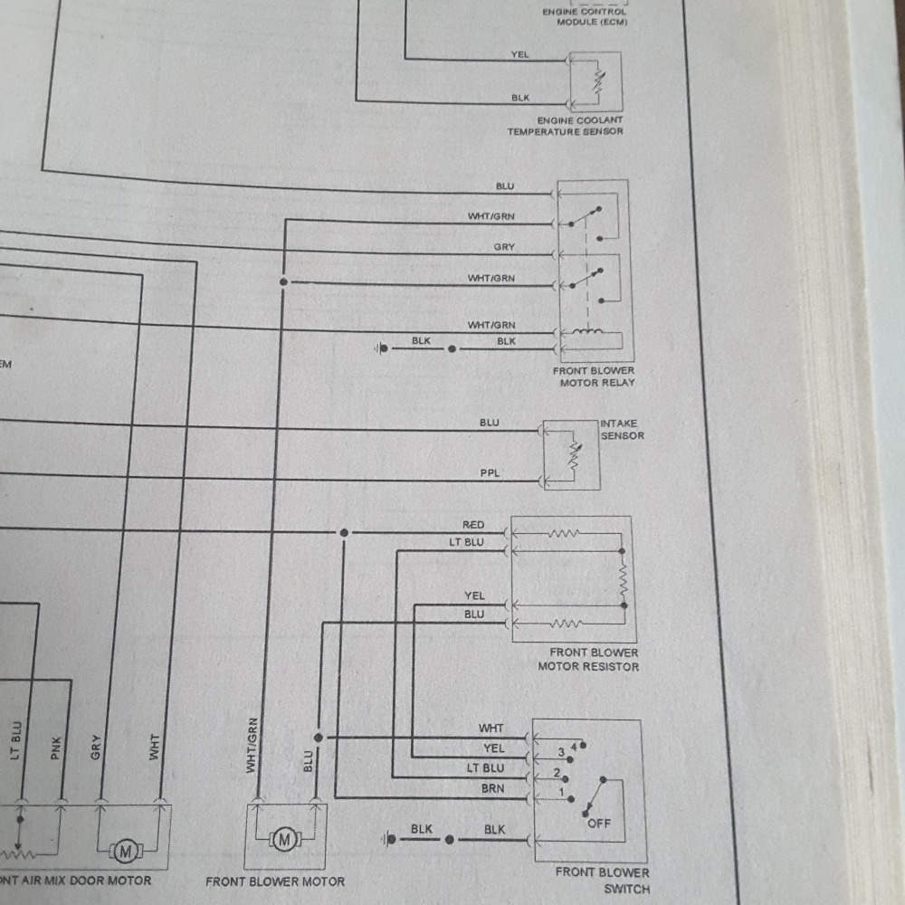
Just running through all your suggestions and looking at the A/C schematics in the Chilton manual and thought if I probe the blower motor connector with my LoadPro tool from Dan Sullivan and cycle through all the blower switch settings while observing the voltage changes it would only tell me if I have an open or a short to ground or resistance in the wiring but would not take into accounnt the A/C relay and signal wiring of that part of the system, right?
Please Log in or Create an account to join the conversation.
- Hardtopdr2
-
- Offline
- Platinum Member
-

- Posts: 853
- Thank you received: 150
Can you get a closer pic of that wiring diagram? Not sure but it looks like it is ground side switched.
What i can tell is from the fuse it feeds into the relay then to the blower motor followed by the blower motor resistor then through the fan speed switch and finally to ground.
If that is the case check for voltage on the relay side of blower motor connection if you have power there and that voltage goes higher to (battery voltage) when it acts up then the switch assembly is the problem. If it drops to 0 when it acts up its a relay. To rule out a relay sway a good one from another circuit that you dont use like high beams or something and see if it still happens. From what i am seeing its relay or switch depending on the result.
Please Log in or Create an account to join the conversation.
- forumjoe
-
Topic Author
- Offline
- Junior Member
-
- Posts: 26
- Thank you received: 1
attached are two pics of the wiring diagram as requested. I see where you are going and I think I can test that by disconnecting the blower motor connector and reading the white/green terminal on a DVOM for voltage. I am having trouble locating the blower motor relay in the engine room, maybe it is located in the passenger room. Anyway thanks for keeping on with the diagnosis and I will try to do what you suggest, it is an intermittent issue though so I will have to wait til it won't work again to test, that shouldn't be long though. But the blower motor blows in all speed settings it is the A/C that stops working in speeds 2 and 3, the A/C button light does not come on or it flickers and will either go out and the compressor stops working or it will stay on and I have A/C working.
Thanks Again Htop
Joe
Please Log in or Create an account to join the conversation.
- forumjoe
-
Topic Author
- Offline
- Junior Member
-
- Posts: 26
- Thank you received: 1
As I thought my ThinkDiag scan tool would not let me access the BCM I played around some more with it today and found that I could in fact access the BCM. Turns out when the A/C is out on #2 and#3 settings the BCM is seeing a fan switch off and an A/C switch off message however when the A/C switch flickers the A/C switch shows on momentarily and the fan blower switch shows off, when the A/C IS working on either #2 or #3 setting both the signals to the BCM show on ( A/C and fan blower switch). But the fan never goes off no matter what the BCM sees. What do you think?
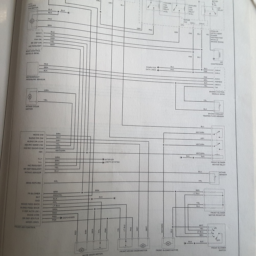
Looking at the schematics it seems it could be the brown wire connection to the red wire in the Front Air Control wiring or the red wire in the BCM, somewhere there is a no fan signal being sent to the BCM even though the fan motor is actually blowing, it wouldn't be anything relating to the resistor pack would it?
Joe
Please Log in or Create an account to join the conversation.
- Hardtopdr2
-
- Offline
- Platinum Member
-
- Posts: 853
- Thank you received: 150
Please Log in or Create an account to join the conversation.
- forumjoe
-
Topic Author
- Offline
- Junior Member
-
- Posts: 26
- Thank you received: 1
joe
Please Log in or Create an account to join the conversation.
- Hardtopdr2
-
- Offline
- Platinum Member
-
- Posts: 853
- Thank you received: 150
Having said that i believe your control panel has the issue but the only other thing that can shut a/c off like that is a pressure switch on the high side line or low side line. Which you should be able to confirm with scan tool or a set of r134 refrigerant gauges. The data pids will say psi reading if your scanner has that ability
Please Log in or Create an account to join the conversation.
- forumjoe
-
Topic Author
- Offline
- Junior Member
-
- Posts: 26
- Thank you received: 1
I really appreciate your diligence on helping me diagnose this problem before I start throwing parts at it. That said, I am thinking if this is an intermittent problem and sometimes the, A/C works on those 2 settings wouldn't that eliminate the pressures in the system? Because it works when it wants to I am thinking front control module, relay(s), wire connection or maybe corrosion somewhere. Do you agree? I will check the pressures at the BCM if I can. What is bothering me is that the fan on signal to the BCM is coming from the red wire that is connected to the brown wire from the resistor pack in the schematics if you notice that. When the A/C doesn't work the BCM has a fan off indication, but the fan is blowing.
I am fortunate that it always works on the highest setting so I am not without A/C altogether and I can take the time to figure out what the problem is, I hope you don't get tired of my questions and I am glad you are still with me.
joe
Please Log in or Create an account to join the conversation.
- Matt T
-
- Offline
- Platinum Member
-
- Posts: 751
- Thank you received: 276
forumjoe wrote: Okay but I know power must be getting to the fan switch because the blower never quits it stays running on all speeds, the BCM thinks that the blower fan is off, but it is not, and I think the AC turns back off if it thinks that the blower fan is off,as the BCM says it is.
joe
It appears that the FAC is turning off AC because it thinks the blower is off. The BCM blower input is grounded, for fan on, either by the fans #1 speed wire or by the FAC. The OEM SI shows both "options" but it really doesn't matter which is correct at this point. Though it's bugging me so I'd have to poke around with the DMM to confirm how it really works.
The FAC is probably also looking for 0V on the fan speed #1 leg to detect that the blower is on. You need to get on the back of the FAC and take voltage readings on that wire at the blower switch. You'll probably see some voltage, to ground, on that wire in the 2 and 3 speed positions which is making the FAC think the blower is off. Most likely caused by bad blower switch contacts though there are other less likely possibilities so take some measurements and report back.
And since you seem reluctant to go after the FAC maybe this video will help.
Please Log in or Create an account to join the conversation.
- Tyler
-

- Offline
- Moderator
-

- Full time HACK since 2012
- Posts: 6126
- Thank you received: 1542
Mostly trying to decide how this circuit is supposed to work... I feel like the key is in here?
It would seem to me that the BCM is providing a 5V signal on the FR BLOWER circuit, and is looking for the FAC (or the blower resistor/switch?) to pull it down to signal that the fan is on. But this whole chart makes no mention of the resistor or the switch.

Please Log in or Create an account to join the conversation.
- Matt T
-
- Offline
- Platinum Member
-
- Posts: 751
- Thank you received: 276
Tyler wrote: It would seem to me that the BCM is providing a 5V signal on the FR BLOWER circuit, and is looking for the FAC (or the blower resistor/switch?) to pull it down to signal that the fan is on. But this whole chart makes no mention of the resistor or the switch.
Yeah the SI sure is contradictory on this one. If the #1 speed leg and BCM blower input really are wired together it'll read battery voltage with the blower off not 0V or 5V.
Please Log in or Create an account to join the conversation.
- forumjoe
-
Topic Author
- Offline
- Junior Member
-
- Posts: 26
- Thank you received: 1
joe
I am thinking if I use my Power Probe to send a ground to the #1 switch contact while I am watching the BCM signals with my Think Diag hooked up after I access the FAC switch contacts that would lead to an almost solution if the BCM shows Fan On signal after I ground the switch contact for #1 setting as that is seemingly the route it uses to the BCM for fan and A/C signals. Then if I remove the ground from the #1 switch contact and the signal @ BCM says fan off it probably is the switch contact. Or it could be the Brn or Red signal wire.
Do you guys agree?
Please Log in or Create an account to join the conversation.
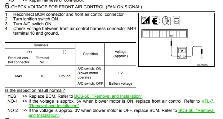
- Tutti57
-

- Offline
- Platinum Member
-
- Posts: 1098
- Thank you received: 253

Nissan Technician
Please Log in or Create an account to join the conversation.
- forumjoe
-
Topic Author
- Offline
- Junior Member
-
- Posts: 26
- Thank you received: 1
thanks for the diagram, it is a little hard to make out on screen, but I am not sure that is where i need to check. The blower fan works but my BCM says it is OFF, when the problem shows up. Again it is intermittent because i can get it to operate correctly sometimes. I am thinking it is a ground problem or an intermittent open or corrosion in the wiring from the fan switch to the BCM. I am hesitant opening up the Fan Control Switch for testing, I don't want to make it worse while it is so hot out, as it always works on #4 fan setting. I do get a little A/C switch light flickering (from time to time on the #4 setting) but it always works.
As for factory info I could use a ground location chart for the blower fan control switch and that system if that is possible.
Thanks and stay tuned,
Joe
Please Log in or Create an account to join the conversation.
- Tutti57
-
- Offline
- Platinum Member
-
- Posts: 1098
- Thank you received: 253
I'm working tomorrow so I'll try to remember to look up that ground location. I think I briefly saw mention of there being two different types of manual AC setups on these trucks too for some reason.
Those four cylinder 2wd are super rare here. I think I've only seen two ever come in.
Nissan Technician
Please Log in or Create an account to join the conversation.
- forumjoe
-
Topic Author
- Offline
- Junior Member
-
- Posts: 26
- Thank you received: 1
OK thanks for going through the trouble, I am seeing the #4 A/C button Light setting also flickering more than it has been in the past, it didn't use to flicker at all, but today it seems to be an issue now too. Now when I have my ThinkDiag scantool hooked in it shows the fan signal as being off whenever the light flickers as well as the A/C switch which I assume automatically turns itself off if it doesn't get the Fan ON signal. The schematics show power going directly to the Blower motor and not through the resistor pack for Fan setting #4, SO THE FLICKERING MIGHT BE A BAD GROUND OR CORROSION at the Fan Control Switch or relay but the fan still blows on Speed #2,3 &4 on speed #1 the fan seems to be on or off intermittently, like sometimes I feel air flow on#1 and sometimes I don't, could that still be in the resistor pack? Or could it be the signal wiring at fault. There is something for you to think about.
What do you think?
joe
Please Log in or Create an account to join the conversation.
- Hardtopdr2
-
- Offline
- Platinum Member
-
- Posts: 853
- Thank you received: 150
Please Log in or Create an account to join the conversation.
- forumjoe
-
Topic Author
- Offline
- Junior Member
-
- Posts: 26
- Thank you received: 1
Thanks, I am not sure where to connect the wire for #1 setting. I think you are telling me to backprobe the #1 resistor pack wire to ground and read the ohms on the multimeter with the key in the off position, but based on the schematics I only see one wire going IN to the resistor for #1 fan switch setting. Am I missing something? You mention 2 wires for the #1 setting at the resistor. What don't I see?
Do you mean to back probe the red wire going in to the resistor and the blue wire going out to the fan motor, with T pins and take voltage readings there? As well as the other resistor wires and the blue wire to take voltage reads for all three resistor settings with the fan in each speed setting with the key in ON , engine either off or on.
Please Log in or Create an account to join the conversation.
- Hardtopdr2
-
- Offline
- Platinum Member
-
- Posts: 853
- Thank you received: 150
Ohm testing speed one will ohm all three resistors in resistor pack.
Ohm testing Speed 2 will ohm test two resistors in resistor pack
Ohm testing speed 3 will ohm test one resistor in resistor pack.
If one of the resistors is failing the ohm reading will say OL for out of limit meaning its open or it will read way higher than 3 times the reading of one resistor.
Please Log in or Create an account to join the conversation.