2009 Nissan Frontier Intermittent A/C on 2 and 3 speed fan setting
- forumjoe
-
 Topic Author
- Offline
- Junior Member
-

- Posts: 26
- Thank you received: 1
thank you
Forumjoe
Please Log in or Create an account to join the conversation.
- Hardtopdr2
-
- Offline
- Platinum Member
-

- Posts: 853
- Thank you received: 150
Now to expand on the blower motor resistor 4 speed will not have a resister slowing current flow. So if 4 speed works all the time and rhe other speeds are intermitant or not at all then i would lean that way. However with the a/c clutch be disabled that make me think the fan switch has an issue with either power feed or an open in the switch. So with the switch when it acts up see if your power feed is being interupted to the switch or if the is a problem with the power going through the switch.
Please Log in or Create an account to join the conversation.
- Tyler
-

- Offline
- Moderator
-

- Full time HACK since 2012
- Posts: 6117
- Thank you received: 1540
It's a shared circuit between the resistor, the FAC and the BCM. I can't find any reference to it in SI.
 But I can't help but wonder if it's involved, given that the blower continues to work even when the clutch is disengaged.
 Please Log in or Create an account to join the conversation.
- Tyler
-
- Offline
- Moderator
-
- Full time HACK since 2012
- Posts: 6117
- Thank you received: 1540
I'd be very interested to check the voltage at pin #1 of the blower resistor while cycling through the fan speeds. Do you have a scan tool capable of communicating with the BCM?
Please Log in or Create an account to join the conversation.
- forumjoe
-
Topic Author
- Offline
- Junior Member
-
- Posts: 26
- Thank you received: 1
Thanks for the input.
joe
Please Log in or Create an account to join the conversation.
- forumjoe
-
Topic Author
- Offline
- Junior Member
-
- Posts: 26
- Thank you received: 1
Thanks for the reply I think I was thinking the same thing as the resistor pack only controls the blower motor speeds I assume and has no effect on the A/C compressor lights on or off, but I don't know for sure if they are indeed connected through some of the other modules as Tyler seems to be suggesting. What do you think?
forumjoe
Please Log in or Create an account to join the conversation.
- Hardtopdr2
-
- Offline
- Platinum Member
-
- Posts: 853
- Thank you received: 150
A manual setup which has dials with blue and red color looking like a yin and yang will be manual a/c which most times will not have a a/c module. This setup will be run as far a data parameters though the bcm module and should have a a/c request signal wire from a/c controller to bcm. The signal for the clutch to kick on will be sent when fan switch is turned on when a/c switch is on. Whichever occurs last. This is why i suggested to look at fan speed switch (power feed and power to blower motor feed to isolate and determine if its the switch, the a/c button or the module that gets the a/c signal.
My hunch would be the switch is causing the issue however powers and grounds checks of bcm/a/c module if auto a/c. Typical problem areas are where water has been getting in like front floor board area ground points or near heater core/ cabin air filter area.
Please Log in or Create an account to join the conversation.
- forumjoe
-
Topic Author
- Offline
- Junior Member
-
- Posts: 26
- Thank you received: 1
It is a manual setup, If I probe the blower motor connector at the motor should I get a power signal with a test light no matter what my switch is set at #1 - #4 ? and should I get a DVOM reading of different volts at the resistor connector? would that help to isolate where the problem is? Did you see my latest reply to Tyler? I drove it yesterday and A/C worked on both the #2 and #3 speed settings and I could not get it to fail. Bumped, jostled, bounced vehicle to try to get it to fail it didn't. I did run a system scan with my ThinkDiag scan tool before I drove it though. It would not communicate with the HVAC module however but maybe it reset something, I don't really think so though just a coincidence maybe. As for testing the BCM I am not sure where that is located to see if there is a signal when A/C is requested also where is the FAC located? Engine room or inside under dash?
Thanks
keep thinking
forumjoe
Please Log in or Create an account to join the conversation.
- Matt T
-
- Offline
- Platinum Member
-
- Posts: 751
- Thank you received: 276
Tyler wrote: Scratch that, I did find something in SI! HAC-108 describes checking for an inop clutch, and goes into checking this circuit specifically. It also has you checking BCM scan data PIDs.
I'd be very interested to check the voltage at pin #1 of the blower resistor while cycling through the fan speeds. Do you have a scan tool capable of communicating with the BCM?
The diagram on HAC-109 and circuit check on HAC-110 doesn't match the full wiring diagram on HAC-120 showing the branch off to the speed #1 circuit. And although it's shown as an external splice it might actually be an internal connection inside the FAC. If it exists at all.
It does sound like the FAC is turning off AC because it thinks the blower isn't on. BCM PIDs would be nice to have but I don't think they're really necessary since the AC light is turning off. Will take voltage checks to figure out what the heck is going on. Ideally on the FAC but if the resistor is easier to access start there.
Joe,
The FAC is the HVAC controls in the dash. It doesn't appear to be networked so you're not going to see it with a scan tool.
Here's a link where you can get the factory SI Tyler and I are referring to.
www.nicoclub.com/nissan-service-manuals
Please Log in or Create an account to join the conversation.
- Hardtopdr2
-
- Offline
- Platinum Member
-
- Posts: 853
- Thank you received: 150
I did see your post to tyler and with it being intermittent this could be a corrosion issue (power and ground wires) , a contact issue with switches or relays, a bad module, or a bad wire.
Since it is a manual a/c it should not have a a/c module however the mitchell diy site will tell you if it does have one or not. If it does then it could be that module is bad or has a power or ground problem.
Please Log in or Create an account to join the conversation.
- forumjoe
-
Topic Author
- Offline
- Junior Member
-
- Posts: 26
- Thank you received: 1
I appreciate your efforts and the knowledge is a great help to me as I do not have the high level scan tools that some do. Thanks for the links you guys posted I will do some more research and see if the A/C stops again and let you know.
Please Log in or Create an account to join the conversation.
- Matt T
-
- Offline
- Platinum Member
-
- Posts: 751
- Thank you received: 276
forumjoe wrote: Thanks Matt, Tyler and Hardtopdr2,
I appreciate your efforts and the knowledge is a great help to me as I do not have the high level scan tools that some do. Thanks for the links you guys posted I will do some more research and see if the A/C stops again and let you know.
Don't let the lack of a scan tool discourage you. It's really not needed for this. A DMM should be enough to figure out what's going on.
I also agree with Hardtopdr2 about getting an aftermarket single vehicle SI subscription. It might help clarify how the blower monitoring really works on this thing.
Please Log in or Create an account to join the conversation.
- forumjoe
-
Topic Author
- Offline
- Junior Member
-
- Posts: 26
- Thank you received: 1
Thanks for giving me the knowledge.
forumjoe
Please Log in or Create an account to join the conversation.
- forumjoe
-
Topic Author
- Offline
- Junior Member
-
- Posts: 26
- Thank you received: 1
Please Log in or Create an account to join the conversation.
- Hardtopdr2
-
- Offline
- Platinum Member
-
- Posts: 853
- Thank you received: 150
Please Log in or Create an account to join the conversation.
- forumjoe
-
Topic Author
- Offline
- Junior Member
-
- Posts: 26
- Thank you received: 1
It is a light in the A/C button I would think an led, I will ty to trace it to the module if I can find the module and read the wire in the schematics. Thanks I will try.
Joe
Please Log in or Create an account to join the conversation.
- Matt T
-
- Offline
- Platinum Member
-
- Posts: 751
- Thank you received: 276
forumjoe wrote: Hardtopdr2,
It is a light in the A/C button I would think an led, I will ty to trace it to the module if I can find the module and read the wire in the schematics. Thanks I will try.
Joe
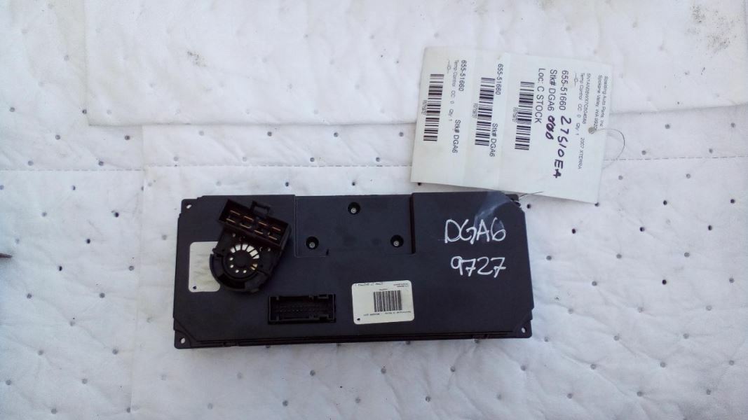
Your HVAC controls are the module, and the blower control switch. Hopefully you'll see a picture of the back side of it I borrowed from ebay, The connector top left with the spade terminals is your blower switch. Since factory SI doesn't do a good job of explaining how the blower monitoring really works you need to backprobe the terminals on the FACs blower switch connector and see if they're all reading 0V to B-, or close to it, when the AC light is off but should be on.
Please Log in or Create an account to join the conversation.
- forumjoe
-
Topic Author
- Offline
- Junior Member
-
- Posts: 26
- Thank you received: 1
Thanks Matt,
joe
Please Log in or Create an account to join the conversation.
- forumjoe
-
Topic Author
- Offline
- Junior Member
-
- Posts: 26
- Thank you received: 1
Just running through all your suggestions and looking at the A/C schematics in the Chilton manual and thought if I probe the blower motor connector with my LoadPro tool from Dan Sullivan and cycle through all the blower switch settings while observing the voltage changes it would only tell me if I have an open or a short to ground or resistance in the wiring but would not take into accounnt the A/C relay and signal wiring of that part of the system, right?
Please Log in or Create an account to join the conversation.
- Hardtopdr2
-
- Offline
- Platinum Member
-
- Posts: 853
- Thank you received: 150
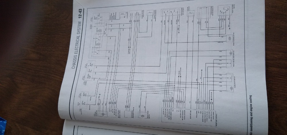
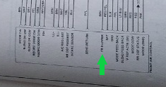
Can you get a closer pic of that wiring diagram? Not sure but it looks like it is ground side switched.
What i can tell is from the fuse it feeds into the relay then to the blower motor followed by the blower motor resistor then through the fan speed switch and finally to ground.
If that is the case check for voltage on the relay side of blower motor connection if you have power there and that voltage goes higher to (battery voltage) when it acts up then the switch assembly is the problem. If it drops to 0 when it acts up its a relay. To rule out a relay sway a good one from another circuit that you dont use like high beams or something and see if it still happens. From what i am seeing its relay or switch depending on the result.
Please Log in or Create an account to join the conversation.