*** Restricting New Posts to SD Premium Members ONLY *** (09 May 2025)
Just made a new account? Can't post? Click above.
2009 MINI: got a stuck lean O2 sensor, am I diagnosing it right? (code: P2195)
- MinionDK
-
 Topic Author
- Offline
- New Member
-

- Posts: 10
- Thank you received: 0
")
Little info about the car:
Mini Cooper, 2009, euro version
40.000 miles on the clock
Engine: 1.4, 4 cylinder
MAP ONLY engine, no MAF
O2 sensors: upstream: wideband, downstream: regular narrowband
The short story:
Long term fuel trim stuck at -0.8 and never switches, short term within ±10%. O2 fixed lean code, though O2 sensor reacts when forced rich. Very low on power when cold (first 10 min. drive). Hunting idle (fluctuating). Exhaust gas analyser shows very high hydrocarbons (HC), terrible MPG. Car doesn’t stay in closed loop.
So few things pointing in different directions, right?
Here’s what I have done so far:
1) I have read out these fault two codes, one of which was pending:
P2195: 02 Sensor Signal Stuck Lean
P0139 (pending, then disappeared): 02 Sensor Circuit Slow Response
Freeze frame for P2195 (stuck lean):
Fuel status: Closed loop
Calculated engine load: 78%
Coolant temp: 221°F (105°C, at operating temp)
STFT: -1.6%
LTFT: -0.8%
RPM: 1.700
Speed: 35m/h (56 km/h)
Absolute throttle position: 28%
Link to freeze frame screenshot:

2) Emissions: I had a friend of mine hook up a gas analyser to the exhaust.
The results: high O2 and hydrocarbons
Hydrocarbons (HC): 463
CO: 0.53
CO2: 15.72
O2: 15.72
3) Fuel status: engine starts in open loop when cold and switches into closed loop, as you would expect. But things go haywire from here: it goes into “closed loop fault” after few minutes - my other scan program calls it “closed loop (O2 sensor fault)”.
Let it idle a bit more and it will spontaneously go into open loop. Throttle snaps will consistently force the system into open loop mode and the car shakes noticeably on the way down (deceleration). It says in closed loop if the RPM is raised slowly.
Here are some videos I recorded of my scan tool:
With the CEL on and car at speed:
Full video: streamable.com/8ji42t
Cleared CEL, left car at idle, revving it up occationaly, here’s the video:
What is going on with the downstream O2 sensor? Edit: fault code is back under pending.
Full video: streamable.com/iaixcn
Screenshot:

Having taken a look at the data, here’s my questions:
Is my wideband upstream O2 sensor faulty?
I’m able to drive the system rich with starter fluid: lambda value (equivalence ratio) goes under 1 (rich) and comes back up and it does stay above 1 (lean) in
Do I have a fuel issue?
High HC is a sign of unburnt fuel, but I have a lean code. Can burning oil cause it as well? I had the car for about 3 months and it does burn oil.
Do I have a vacuum leak?
With the STFT switching somewhat normaly I haven't got much to go on. As I understand it, a vacuum leak in MAP only engine shouldn’t have a big impact on fuel trims and thus shouldn’t cause a lean code (car will idle high, though). My STFT is ±10%, but LTFT is fixed at -0.8% (kept an eye on it for the past 10 days)
Is my MAP sensor bad?
I haven’t found a wiring diagram, but testing the sensor is my next step. Would you suspect a bad MAP sensor in these conditions? (remember no MAF)
Any help will be much appreciated.
Thank you
Please Log in or Create an account to join the conversation.
- tech25
-
- Offline
- Premium Member
-

- Posts: 86
- Thank you received: 27
Please Log in or Create an account to join the conversation.
- MinionDK
-
Topic Author
- Offline
- New Member
-
- Posts: 10
- Thank you received: 0
@tech25: I added some info at the top of the post. It's not a US car, a VIN wouldn't be much of a help. Let me know if I left something out.
Please Log in or Create an account to join the conversation.
- tech25
-
- Offline
- Premium Member
-
- Posts: 86
- Thank you received: 27
by your diagram you found on tis, it shows a r56.. but you say it has a 1.4 litre engine..?? are you sure its not a 1.6?
a vin would help.
Please Log in or Create an account to join the conversation.
- MinionDK
-
Topic Author
- Offline
- New Member
-
- Posts: 10
- Thank you received: 0
@tech25: Check your pm.
Please Log in or Create an account to join the conversation.
- tech25
-
- Offline
- Premium Member
-
- Posts: 86
- Thank you received: 27
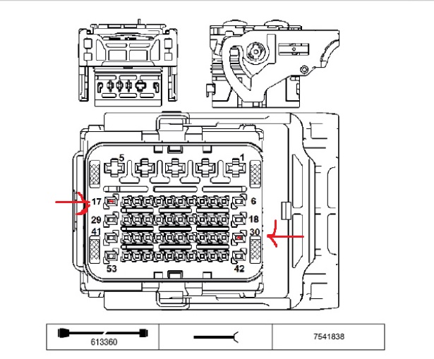
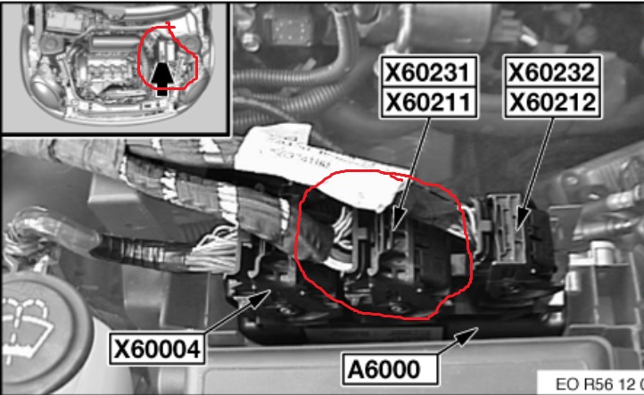

Hey there... thanks for the PM.. Ok... I would first measure the resistance of the heater element in the pre 02 sensor with a DVOM. Do this by disconnecting connector X60211 on the DME. then looking at the pins 17 and 30 Measure the resistance ( ohms ) from those pins, should be around 3.5 - 4.0 ohms.
see included pics for connector and pin locatons.
Please Log in or Create an account to join the conversation.
- MinionDK
-
Topic Author
- Offline
- New Member
-
- Posts: 10
- Thank you received: 0
If I wanted to test the MAP sensor, how would go about that? I only have a DVOM and a wiring diaat my disposal. So much joy in learning new things
*Edit: Any idea why my Long Term Fuel Trim would be fixed? it's -0.8 regardless of driving conditions
Please Log in or Create an account to join the conversation.
- tech25
-
- Offline
- Premium Member
-
- Posts: 86
- Thank you received: 27

I wouldnt really worry about that now... test the 02 sensor, and probably replace. however if you want to test. maybe you can. but not really well. you either have a analog sensor, and a digital sensor. I'm not sure what one you have.
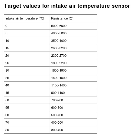
however you can back probe either pin 1, or 3 and see what you get. one is the temp sensor, and one is the map sensor.
check resistance according to the chart from measuring resistance from pin 2, and to pin 1 or 3 and see if any reading is close to the enclosed chart.
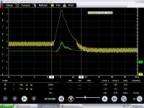
I attached a pico scope explanation on how you can kinda test it. normally with key on, engine off around 5v, and with engine at idle under a vacuum around 1.0v.
if you have have a digital sensor you have to measure the hz. edit... picture of 12v is probably not true, more likely 5v
Please Log in or Create an account to join the conversation.
- MinionDK
-
Topic Author
- Offline
- New Member
-
- Posts: 10
- Thank you received: 0
I finally got a chance to carry out the tests on the O2 heater circuit.
I disconnected battery negative terminal before I began.
DME: pins 17 and 30 are reading O.L.
Sensor connector: unplugget it and measured resistance between pins 3 and 4 few times in the space of 5 minutes - got between 3.7Ω and 3.9Ω.
Should I suspect an open in the harness?
Also, I found some nice troubleshooting notes for the older Bosch LSU 4.2, not sure if the wiring and ohms differ from mine (LSU 4.9)


Please Log in or Create an account to join the conversation.
- MinionDK
-
Topic Author
- Offline
- New Member
-
- Posts: 10
- Thank you received: 0
I added this bit to my previous message:
I found some nice troubleshooting notes for the older Bosch LSU 4.2, not sure if the wiring and ohms differ from mine (LSU 4.9)
Please Log in or Create an account to join the conversation.
- MinionDK
-
Topic Author
- Offline
- New Member
-
- Posts: 10
- Thank you received: 0
I don't have bidirectional control. Having the engine ON might be the condition for the heater to be on. Is that an option for the ground check (back probing)?
Ok, so to elaborate on my last test: pin 30 & 17 on the PCM gave me OL, then I went down to the sensor connector, disconnected it, and measured sensor side (my 2nd picture) terminal 3 & 4 which had the proper resistance as specified. Would that be an open heater circuit or open in the wiring harness to the PCM? Just want to make sure there was no lack of clarity as to what I did, before we condemn the sensor.
Please Log in or Create an account to join the conversation.
- MinionDK
-
Topic Author
- Offline
- New Member
-
- Posts: 10
- Thank you received: 0
A little note: It's a wideband/air-fuel O2 sensor by Bosch (LSU 4.9). I found a datasheet here , it seems to suggest pin 3 and 4 are the heater ±.
I reconnected the battery after ohms testing and checked harness side pin 4 for power, which seems to be fine.
This is what I have tested thus far:

Please advice.
Thank you very much.
Please Log in or Create an account to join the conversation.
- Landroverman1958
-
- Offline
- Premium Member
-
- Posts: 93
- Thank you received: 17
Please Log in or Create an account to join the conversation.
- tech25
-
- Offline
- Premium Member
-
- Posts: 86
- Thank you received: 27
Please Log in or Create an account to join the conversation.
- MinionDK
-
Topic Author
- Offline
- New Member
-
- Posts: 10
- Thank you received: 0
This is what I will check in the morning:
- Leave sensor connected, and check the harness at the PCM. I should be able to read to same 3.5 ohms, unless there is a break, right?
- Disconnect both sensor and PCM, and check the harness for resisance (under 0.7Ω)
In the mean time I have uploaded some videos. Both are recorded at idle, after engine warm up.
Lambda under 1: rich
Lambda 1: ideal
Lambda above 1: lean
1) This one is after I cleared the lean fault. Notice how the upstream and downstream sensors are showing different things (S1 showing rich, S2 pegged lean). What's going on with the downsteam?
streamable.com/iaixcn
2) This is before I cleared the fault. Engine was surging quite a bit.
streamable.com/f56464
I'm not showing Long Term Fuel Trim because it's been fixed at -0.8 for weeks.
Thanks again, guys.
Please Log in or Create an account to join the conversation.
- MinionDK
-
Topic Author
- Offline
- New Member
-
- Posts: 10
- Thank you received: 0
I didn't much luck detecting any leaks by spraying starter fluid around the hoses and the intake gasket.
Next step is to have my local shop hook up my their smoke machine and look for leaks.
Any of you good people able to get your hands on the specs for my MAP sensor?
Bosch part number: 0261230136
www.boschautoparts.com/en/auto/pressure-...rs?partID=0261230136
Please Log in or Create an account to join the conversation.