1993 3.1L Injector shorts or shorted ECM?
- norman.wilson
-
 Topic Author
- Offline
- New Member
-

- Posts: 13
- Thank you received: 0
Please Log in or Create an account to join the conversation.
- norman.wilson
-
Topic Author
- Offline
- New Member
-
- Posts: 13
- Thank you received: 0
Please Log in or Create an account to join the conversation.
- Noah
-

- Offline
- Moderator
-

- Posts: 5028
- Thank you received: 1119
Thankfully, I've never had to tangle with this system for an injector issue. SacnnerDanner has done a good job describing the testing methods and has some good videos outlining the diagnosis.
Here's one of them:
As far as your voltage measurements are concerned, it would be perfectly normal to see battery voltage on both sides of the injector with the key on and the engine off. The injectors are not being commanded on, so the circuit is incomplete (not being closed by the pcm), so there can be no voltage drop in the circuit.
Here is another free video that illustrates that concept well:
Please Log in or Create an account to join the conversation.
- norman.wilson
-
Topic Author
- Offline
- New Member
-
- Posts: 13
- Thank you received: 0
Please Log in or Create an account to join the conversation.
- Noah
-
- Offline
- Moderator
-
- Posts: 5028
- Thank you received: 1119
If you haven't already, I would check fuel pressure next, to see if fuel is available for the injectors to spray.
Also, how do you know the injectors aren't pulsing? Did you check them with a noid light or test light or some thing? I'm not picking apart your diagnostic method, just trying to get up to speed with where you are.
Please Log in or Create an account to join the conversation.
- norman.wilson
-
Topic Author
- Offline
- New Member
-
- Posts: 13
- Thank you received: 0
Please Log in or Create an account to join the conversation.
- norman.wilson
-
Topic Author
- Offline
- New Member
-
- Posts: 13
- Thank you received: 0
Please Log in or Create an account to join the conversation.
- Noah
-
- Offline
- Moderator
-
- Posts: 5028
- Thank you received: 1119
and California emissions, which has the Sequential injection.
It will say which version on a sticker affixed under the hood, on the radiator support, or possibly even on a strut tower.
It should say something to the effect of "this vehicle conforms to { U.S. EPA regulations} or {California emission standards} in effect for model year production.
Please Log in or Create an account to join the conversation.
- norman.wilson
-
Topic Author
- Offline
- New Member
-
- Posts: 13
- Thank you received: 0
Please Log in or Create an account to join the conversation.
- norman.wilson
-
Topic Author
- Offline
- New Member
-
- Posts: 13
- Thank you received: 0
Please Log in or Create an account to join the conversation.
- norman.wilson
-
Topic Author
- Offline
- New Member
-
- Posts: 13
- Thank you received: 0
Please Log in or Create an account to join the conversation.
- Noah
-
- Offline
- Moderator
-
- Posts: 5028
- Thank you received: 1119
Ok, so I've been checking out what the ESC function is. It seems like it is only part of the knock sensor circuit. The ESC, (which only seems to be designated as such on the California emissions model), is integrated into the PROM portion of the PCM. Those must be the screws you're having a hard time with.
The PCM supplies 5v, which is pulled down by the knock sensor circuitry to around 2.5v.
The knock sensor creates an AC voltage which rides over that 2.5v, which is interpreted by the PCM to retard ignition timing in increments of 10 degrees depending on the severity of the knock.
It's doubtful that the ESC would would have any effect on injector pulse. I don't think that even if this 5v supply was shorted to ground it would cause anything more than a CEL, since the circuit is designed to be pulled (partially) to ground. Almost like a thermistor circuit.
I noticed that you have checked for injector pulse with a noid light, which is a valid test, and in fact how the service information would have you check it. The only issue I have with a noid light is that in only proves the injector isn't being controlled. It doesn't let you know where the problem is, on the power side or the control side.
You mentioned that you bypassed the fuse to the injector power supply because either the fuse was melted or the female pins were melted? I agree that that is most likely due to the short to ground you discovered. Thankfully, a short to ground on the power supply to the injectors most likely wouldn't have harmed the PCM. It also appears that, at least depending on where you have the wire bypassed, it should be only the power lead to the injectors and nothing else.
A voltage drop in this leg of the circuit would mean that the injectors aren't getting power under load, which would result in no activity from the noid light. Ideally you would want to check voltage here (at the positive lead to any injector), with a voltmeter and the injector connected while cranking the engine.
You could also load the circuit with a light bulb if that's easier. Key on engine off, connect one lead of the bulb to the injector power wire and the other lead of the bulb to ground, (injector disconnected). A good bright light would prove the power feed to the injectors is not dropping out under the demand of the injectors.
As far as inputs, the PCM checks the Engine Coolant Temperature (ECT) sensor, the Throttle Position Sensor (TPS) and the Crank Position Sensor (CKP), to determine injector pulse width.
If the pcm sees the TPS at >65%, it will cut injector pulse. This is clear flood mode. Paul has mentioned this in many videos.
This sensor and related circuitry (including possibly the PCM) could potentially cause the symptoms you describe.
It would be worth it to check for at minimum a 5v supply to the TPS. One of the 3 wires should be 5v, key on engine off. One should be ground, and the last wire (the signal wire) should be low with the throttle closed (probably less than 0.5v) and high with the throttle wide open (4v or more) if you've got higher than normal voltage on the signal wire with the throttle closed (say 3volts or more guesstimate) the PCM will interpret this as Clear Flood Mode and cut the injector pulse.
Also, if you don't have the 5v supply to the TPS, it could be shorted to ground pulling the whole 5v ref down causing your no start.
While an erroneous input from the ECT could cause a no start, it would most likely not entirely cut injector pulse. You'd probably end up with excessive fuel and fouled plugs
A faulty CKP sensor (and circuitry) would result in a no spark scenario.
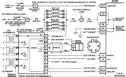
Another fault I could imagine based on this system diagram could be the external PCM grounds dedicated to the injector drivers, or a PCM connector fault at D4 and D10. It looks like that would be ground G104. G104 is bolted to the transmission bellhousing directly opposite the starter solenoid.
So, there's some stuff to digest. If I think of anything or find anything else out, I'll post it up for you.
There may be some stuff I didn't think of.
Please Log in or Create an account to join the conversation.
- Chriscoy
-

- Offline
- Junior Member
-

- Heavy duty truck technician / foreman/ parts guy/
- Posts: 29
- Thank you received: 6
Paul does a great job covering this topic that can be very daunting for a little bit but once you understand it, it's easy.
Hope this link works.
Changing parts is easy, Troubleshooting is an art
Please Log in or Create an account to join the conversation.
- Noah
-
- Offline
- Moderator
-
- Posts: 5028
- Thank you received: 1119
I wasn't recognizing the ignition control module as being in control of the injectors too. I hadn't even considered the ICM. It sure jumped to the top of the suspects list for me.
I was looking at it as the ECM in control of the injectors based on CKP input. Very glad you came in on this one.
Please Log in or Create an account to join the conversation.
- norman.wilson
-
Topic Author
- Offline
- New Member
-
- Posts: 13
- Thank you received: 0
Please Log in or Create an account to join the conversation.
- ScannerDanner
-

- Offline
- Administrator
-

- Religion says do, Jesus says done!
- Posts: 975
- Thank you received: 500
You don't need to have the module tested. With the key on, take a test light to battery positive and touch on and off the purple white wire coming from the module. This the the rpm signal to the ecm. The ecm should react by running the fuel pump and firing the injectors each time.
An alternative test. During cranking there should be a 0/5v on off signal on this same purple white wire. Using a voltmeter will give you an average voltage. Can you give us a voltage reading on this wire?
Don't be a parts changer!
Please Log in or Create an account to join the conversation.
- norman.wilson
-
Topic Author
- Offline
- New Member
-
- Posts: 13
- Thank you received: 0
Please Log in or Create an account to join the conversation.
- Tyler
-

- Offline
- Moderator
-
- Full time HACK since 2012
- Posts: 6124
- Thank you received: 1541
norman.wilson wrote: While I have your attention, I have a 2003 PT Cruiser GT Turbo that I couldn't stop where I was and over heated the engine so bad (no water) it shut down. I tested for compression and there isn't much, and when I crank it she sounds a lil tight. Do you think the engine is worth putting new rings and bearings, or is it toast? Thank you again for all the help.
Hey norman! What were the results of your compression test, exactly? Do you have a leak down tester? May be worth knowing where the compression is going.
Also, please don't hesitate to start a new thread if you're looking for more opinions
") I know other members around here (like Gilbert) have practical bottom end experience.
I know other members around here (like Gilbert) have practical bottom end experience.My first thought, if this is my PT Cruiser, would be to do a long block. Faster, simpler, fewer things for me to get wrong :blush:
Please Log in or Create an account to join the conversation.
- Chriscoy
-
- Offline
- Junior Member
-
- Heavy duty truck technician / foreman/ parts guy/
- Posts: 29
- Thank you received: 6
Changing parts is easy, Troubleshooting is an art
Please Log in or Create an account to join the conversation.
- norman.wilson
-
Topic Author
- Offline
- New Member
-
- Posts: 13
- Thank you received: 0
Please Log in or Create an account to join the conversation.