1997 Tacoma 2.4, No Spark, No Start, Can't Solve. Impossible Fix?

This is what i've found in a quick search
Please Log in or Create an account to join the conversation.
If injector are not firing, neither spark plugs we should focus on if crankshaft signal is getting PCM.
Please Log in or Create an account to join the conversation.
I know the injectors arent firing. I smell no raw fuel in my tail pipe after cranking.
Please Log in or Create an account to join the conversation.
Please Log in or Create an account to join the conversation.
Please Log in or Create an account to join the conversation.
Unplug CKP and check in conector terminals
1. Ground pin: This terminal has continuity with block engine (close to 0 ohms).
2. Power pin: This terminal has voltage once you turn ignition switch on.
3. Signal pin: The one which is not ground, neither power.
Once you identify signal, plug ckp again and check voltage in signal line while cranking. You should see not a constant voltage, but at least a change compare to "no cranking"
Please Log in or Create an account to join the conversation.
But something bad happened. A loud electrical 'snap' sound happened under the hood while I was testing those terminals at the CKP. Now I don't have any power at all.
**edit, now I have power after waiting 5 minutes**. That was weird.
Please Log in or Create an account to join the conversation.
Could that low reading mean failure of an out of the box new sensor?
Please Log in or Create an account to join the conversation.
Remember we are trying figure it out just with a voltmeter. That's why we are doing this. If you get a scope that would be faster.
5.8 volts could be a good average, depending of other factors. Let's complete ckp test with the following:
With ignition switch on (no crank) rotate crankshaft by hand (very slowly). You should be able to see voltage jumping from 0 volts to power source voltage.
It better if you perform this test in ecu connector. That way we can discard sensor and wire at the same time.
Please Log in or Create an account to join the conversation.
- juergen.scholl
-

- Offline
- Platinum Member
-

- Active partschanger
- Posts: 1197
- Thank you received: 446
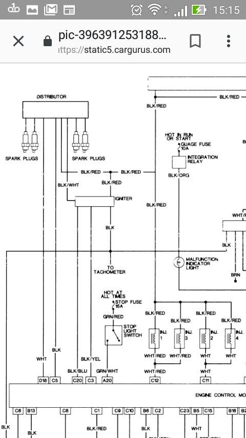
The ckp signal, an AC-sine wave as well, is sent to the ecm at connector E8 as well, entering at pin 4 and 17.
With these inputs the ecm sends a signal to the igniter to activate the ignition coil. This is the IGT signal and enters the igniter at pin2; it's a square wave. The igniter then grounds the primary of the ignition coi through pin 5 at its own connector, accordingly to the IGT signal. Taking away this ground will induce the spark in the secondary.
Once ignition successfully has taken place the igniter sends a confirmation to the ecm. This is the IGF signal and enters the ecm in E8, pin 3.
These are the signals you have to confirm in this pretty straight forward ignition system.....
The ecm won't send further IGT signals if it does not receive the IGF signals, so make sure this circuit is not grounded or open.
Check the mentioned signals/circuits and report your findings.
An expert is someone who knows each time more on each time less, until he finally knows absolutely everything about absolutely nothing.
Please Log in or Create an account to join the conversation.
Juergen, unfortunately, I dont have an ocilliscope to read those signals. This might be something I'm unable to do (determine what signals are what).
Please Log in or Create an account to join the conversation.
Forget about CKP test mentioned by me before (sensor is different)
That means CKP wires are:
1. Noise shield: The terminal which has continuity with engine block.
2. Coil: The two wires which are not ground
You can check AC voltage while cranking between the two coil terminals (same thing in CMP coil terminals mentioned by juergen.
It is supossed that in "no cranking" and ignition switch on, you should no see any voltage
Edit: moving crankshaft by hand, you can't see any voltage, because you need certain speed you can't get by hand
Please Log in or Create an account to join the conversation.
- Andy.MacFadyen
-

- Offline
- Moderator
-

- Posts: 3353
- Thank you received: 1031
" We're trying to plug a hole in the universe, what are you doing ?. "
(Walter Bishop Fringe TV show)
Please Log in or Create an account to join the conversation.
I cant detect any signal at the E8 plug at the ECU / wire 5 or 18 as Juergen suggested. But then again, I'm not using an oscilloscope. No voltage seen, just zeros.
Please Log in or Create an account to join the conversation.
- juergen.scholl
-
- Offline
- Platinum Member
-
- Active partschanger
- Posts: 1197
- Thank you received: 446
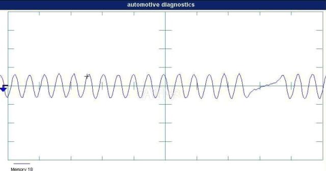
With a sound battery you should get at least 500mV from the ckp while cranking, I'll attach a screen shot from a good sensor, same year, same engine. Engine is running, so the voltage is higher.
DO YOU HAVE THE CORRECT WIRING DIAGRAM?
An expert is someone who knows each time more on each time less, until he finally knows absolutely everything about absolutely nothing.
Please Log in or Create an account to join the conversation.
1. You have to measure AC voltage
2. Measure voltage between pins 4 & 17 (ckp) or 5 & 18 (cmp)
You mentioned "5 or 18" (i suppose you mean one test lead to ground and the other to 5 or 18, which is incorrect)
Please Log in or Create an account to join the conversation.
Please Log in or Create an account to join the conversation.
guafa wrote: Brianzero, just to be clear.
1. You have to measure AC voltage
2. Measure voltage between pins 4 & 17 (ckp) or 5 & 18 (cmp)
You mentioned "5 or 18" (i suppose you mean one test lead to ground and the other to 5 or 18, which is incorrect)
UPDATE:
Ignition in ON position.
I have voltage at pin 4 and 17 (E8 plug on the ECU) It appears to be 0.54v at both pins. These are the CKP pins at the ECU.
Please Log in or Create an account to join the conversation.
So, you don't have spark, neither injection pulse. Seems PCM is detecting something else (or not seeing other signals).
Please Log in or Create an account to join the conversation.
Please Log in or Create an account to join the conversation.