2009 dodge challenger rt with 5.7 engine no crank, no start and no communication
- ChallengerDude
-
 Topic Author
- Offline
- Junior Member
-

- Posts: 26
- Thank you received: 4
Please Log in or Create an account to join the conversation.
- Monde
-
- Offline
- Elite Member
-

- Posts: 220
- Thank you received: 43
Assuming is never a good thing.
Please Log in or Create an account to join the conversation.
- ChallengerDude
-
Topic Author
- Offline
- Junior Member
-
- Posts: 26
- Thank you received: 4
Please Log in or Create an account to join the conversation.
- Monde
-
- Offline
- Elite Member
-
- Posts: 220
- Thank you received: 43
Assuming is never a good thing.
Please Log in or Create an account to join the conversation.
- ChallengerDude
-
Topic Author
- Offline
- Junior Member
-
- Posts: 26
- Thank you received: 4
Please Log in or Create an account to join the conversation.
- ChallengerDude
-
Topic Author
- Offline
- Junior Member
-
- Posts: 26
- Thank you received: 4
Please Log in or Create an account to join the conversation.
- Mathewsowers42
-
- Offline
- New Member
-

- Posts: 9
- Thank you received: 2
Please Log in or Create an account to join the conversation.
- ChallengerDude
-
Topic Author
- Offline
- Junior Member
-
- Posts: 26
- Thank you received: 4
Please Log in or Create an account to join the conversation.
- ChallengerDude
-
Topic Author
- Offline
- Junior Member
-
- Posts: 26
- Thank you received: 4
Been checking the modules that share the can c bus. If I measure at the dlc, I get 2.5v across the can+ and can- wires as well as each can wire with the body ground. When measuring at the shift sensor I only 2.5v when measuring the can+ or can- with the ground. I get about 300mv when measuring across the can- and can+ wires. Not sure if that's normal.
Please Log in or Create an account to join the conversation.
- Monde
-
- Offline
- Elite Member
-
- Posts: 220
- Thank you received: 43
When you get your graphing multimeter, you can scope the can lines at any module and post the result. The graph would help others to help you better.
Assuming is never a good thing.
Please Log in or Create an account to join the conversation.
- ferris48
-

- Offline
- Premium Member
-

- Posts: 129
- Thank you received: 47
I'm going to attribute this difference to the DLC being the Diagnostic CAN C, while the one at the shift sensor being actual CAN C.If I measure at the dlc, I get 2.5v across the can+ and can- wires as well as each can wire with the body ground. When measuring at the shift sensor I only 2.5v when measuring the can+ or can- with the ground. I get about 300mv when measuring across the can- and can+ wires. Not sure if that's normal.
pdfhost.io/v/FuHB30999__2009_Dodge_Chall...IN_T_Des_EZC_16V_OHV
All measurement of termination resistance is done with the vehicle battery disconnected.
The dominant nodes on the CAN-C bus are the WIN and the Powertrain Control Module (PCM). The termination resistance of the two dominant nodes are combined in parallel to provide a total of about 60 Ohms.
Total resistance of the CAN-C network can also be measured (60 Ohms)
If there are intermittent or active faults in the CAN network, a diagnostic scan tool connected to the Diagnostic CAN-C bus through the 16-way Data Link Connector (DLC) may only be able to communicate with the TIPM. To aid in CAN network diagnosis, the TIPM provides CAN-B and CAN-C network status information to the scan tool using certain diagnostic signals.
Please Log in or Create an account to join the conversation.
- ChallengerDude
-
Topic Author
- Offline
- Junior Member
-
- Posts: 26
- Thank you received: 4
Please Log in or Create an account to join the conversation.
- ChallengerDude
-
Topic Author
- Offline
- Junior Member
-
- Posts: 26
- Thank you received: 4
Please Log in or Create an account to join the conversation.
- ChallengerDude
-
Topic Author
- Offline
- Junior Member
-
- Posts: 26
- Thank you received: 4
Please Log in or Create an account to join the conversation.
- ferris48
-
- Offline
- Premium Member
-
- Posts: 129
- Thank you received: 47
totally normal.So what would cause that circuit to go down to 4v when the iat is plugged in? is there a short somewhere that it's taking over sending the voltage through the iat? Or is that normal?
The temp sensor circuit has a current limiting resistor inside the computer so it's perfectly fine to pull that 5v signal straight to ground without affecting the other sensor using the 5v reference circuit. That's why when you're checking for shorted sensors it's useless to unplug temp sensors. But if you want to check for a 5v, you unplug it. If it goes to 5, the 5v ref circuit is probably fine.
Please Log in or Create an account to join the conversation.
- ferris48
-
- Offline
- Premium Member
-
- Posts: 129
- Thank you received: 47
Anything is possible. If it comes to that point, you'd watch the signal waveform to return to normal after unplugging the tipm.Could the tipm produce bad voltage on can c that's keeping the pcm from communicating?
Your previous measurements at the DLC and at the shifter didn't read as too alarming but a waveform wouldn't hurt either
")
Please Log in or Create an account to join the conversation.
- ferris48
-
- Offline
- Premium Member
-
- Posts: 129
- Thank you received: 47
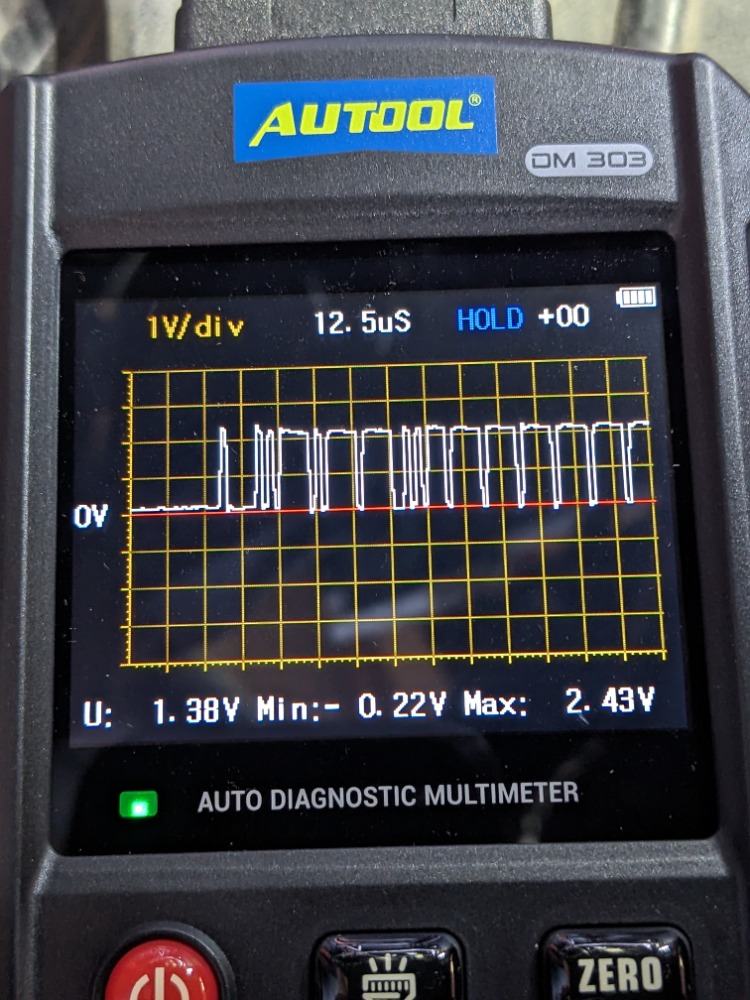
I think you have this single channel scope hooked like this: can high on red lead and can low on black lead. This would explain the absence of the bias voltage. To check for proper bus bias, you'd want to hook up your scope to battery negative.Here's what the can bus from the dlc looks like. Not sure what would cause that wave form.
Please Log in or Create an account to join the conversation.
- Monde
-
- Offline
- Elite Member
-
- Posts: 220
- Thank you received: 43
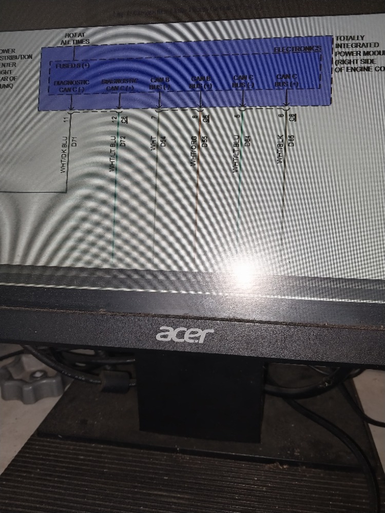
Is that the diagram you have?
Assuming is never a good thing.
Please Log in or Create an account to join the conversation.