P0118 non start issues
- mckenzie
-
 Topic Author
- Offline
- New Member
-

- Posts: 15
- Thank you received: 0
It's a 2009 Peugeot 207s Vti, 1.4l. I have an ongoing no start condition & P0118 code.
Engine was replaced with second hand engine due to suspected piston rings/head gasket. New engine ran good for 1 week, only issue was temp gauge was reading low all the time. Sudden non start occurred after this 1 week. P0118 code read with -40 degrees shown. Codes read with Peugeot specific software, Diagbox.
Found ECT sensor was leaking coolant into its plug.
ECT sensor & plug has been replaced with proper OEM part. Still no start. Strong smell of fuel on cranking.
Wiring integrity from ECT to ECU checked ok. Power & grounds to ECU checked ok.
With ECT unplugged am measuring only 3.3v on sensor reference wire. This measurement is taken with a known good ground also. Back probing from ECU plug directly, still 3.3v.
I'd like to disconnect all other sensors one by one to see if any are pulling the voltage down but many of them are accessed from under the car & the car is not on a suitable surface to jack up safely. Am unsure also if the ECU shares its 5v reference circuits internally in any way.
Any thoughts on what could cause the ECT 5v reference to go to 3.3v ? Maybe the 3.3v rings a bell with someone ?
Sorry for the long ramble. Thanks for any help
Please Log in or Create an account to join the conversation.
- Andy.MacFadyen
-

- Offline
- Moderator
-

- Posts: 3357
- Thank you received: 1037
" We're trying to plug a hole in the universe, what are you doing ?. "
(Walter Bishop Fringe TV show)
Please Log in or Create an account to join the conversation.
- mckenzie
-
Topic Author
- Offline
- New Member
-
- Posts: 15
- Thank you received: 0
If the ECU needs replacing then obviously I need to find out what has caused it to fail if I were to replace it. However I am getting to the stage now where I am having to think hard about getting rid of it, nightmare situation!
Please Log in or Create an account to join the conversation.
- Tyler
-

- Offline
- Moderator
-
- Full time HACK since 2012
- Posts: 6126
- Thank you received: 1542
The last test I can suggest doing is checking the ECT sensor signal wire for a resistive short to ground, which would cause the 5V signal to get partially pulled to ground. You can test for this two ways. One would be to disconnect the ECT and the ECU, and use your ohm meter to check the wire for resistance to B-. There should be ZERO continuity.
The other is to cut the ECT wire close to the ECU connector. Somewhere easily repaired once you fix the issue.
Please Log in or Create an account to join the conversation.
- mckenzie
-
Topic Author
- Offline
- New Member
-
- Posts: 15
- Thank you received: 0
I didn't mention that I already cut the wires close to the ECU & still measured 3.3v. I also managed to probe the ECU pins directly with the connector unplugged, still 3.3v.
I've just taken your advice as well & disconnected b+ & ohm tested from ECT signal wire to B- & I am getting 1.175k.
If your 100% sure that this is conclusive that the ECU has developed an internal fault then I will go ahead & arrange for it to be repaired.
I am still left wondering what has caused it to fail. The way the thermistor circuit works appears that the internal resistor should keep it fairly full proof if anything happens externally , I guess not?
Please Log in or Create an account to join the conversation.
- Andy.MacFadyen
-
- Offline
- Moderator
-
- Posts: 3357
- Thank you received: 1037
" We're trying to plug a hole in the universe, what are you doing ?. "
(Walter Bishop Fringe TV show)
Please Log in or Create an account to join the conversation.
- Tyler
-
- Offline
- Moderator
-
- Full time HACK since 2012
- Posts: 6126
- Thank you received: 1542
mckenzie wrote: I didn't mention that I already cut the wires close to the ECU & still measured 3.3v. I also managed to probe the ECU pins directly with the connector unplugged, still 3.3v.
Oh OK, way ahead of me! :lol: Any evidence of water intrusion in the ECU connector? Green corrosion? This is pretty much the last possibility besides the ECU itself.
I've just taken your advice as well & disconnected b+ & ohm tested from ECT signal wire to B- & I am getting 1.175k.
This is a bit odd... Did you have the ECU and ECT disconnected during this test?
If your 100% sure that this is conclusive that the ECU has developed an internal fault then I will go ahead & arrange for it to be repaired.
I am still left wondering what has caused it to fail. The way the thermistor circuit works appears that the internal resistor should keep it fairly full proof if anything happens externally , I guess not?
That's all I've got, anyway. :silly: I always thought of thermistor circuits as pretty much bulletproof, too. This and another recent thread now have me thinking otherwise.
Please Log in or Create an account to join the conversation.
- mckenzie
-
Topic Author
- Offline
- New Member
-
- Posts: 15
- Thank you received: 0
Sorry, no I didn't completely unplug the ECU with that test, I misunderstood what I was trying to do. So, correction - with ECU + ECT completely unplugged I get zero continuity from reference wire to B-.
To be completely transparent there is always the chance I've followed some incorrect procedure around the car somewhere due to my inexperience & have possibly spiked the ECU some how. I have however tried to follow battery disconnection/reconnection procedure to the book but I may have missed something important early on.
As you say then, looking like the only thing left is the ECU
Please Log in or Create an account to join the conversation.
- Tyler
-
- Offline
- Moderator
-
- Full time HACK since 2012
- Posts: 6126
- Thank you received: 1542
I'd be surprised if anything else you did to the vehicle caused this. Like Andy suggested, I bet this has more to do with a manufacturing issue. But, I've been wrong before! :silly:
Please Log in or Create an account to join the conversation.
- mckenzie
-
Topic Author
- Offline
- New Member
-
- Posts: 15
- Thank you received: 0
Please Log in or Create an account to join the conversation.
- mckenzie
-
Topic Author
- Offline
- New Member
-
- Posts: 15
- Thank you received: 0
Sorry for my lack of knowledge !
Please Log in or Create an account to join the conversation.
- Tyler
-
- Offline
- Moderator
-
- Full time HACK since 2012
- Posts: 6126
- Thank you received: 1542
mckenzie wrote: Actually I've just learned that any 5v thermistor reference cannot be shared with a potentiometer reference. But, could it be shared with another thermistor like the IAT sensor ? It doesn't appear that way on my wiring diagram though, the ECT goes straight to the ECU.
Sorry for my lack of knowledge !
No worries at all!
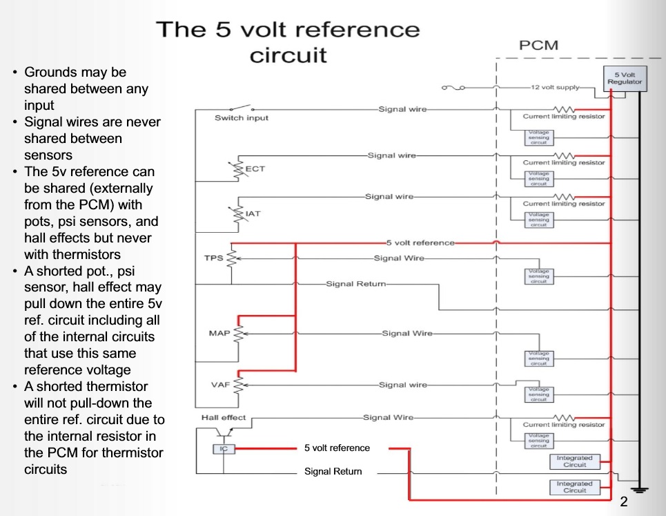
It's the high value resistor (current limiting) on the thermistor signal circuits that makes them unable to be shared with other 5V sensors. It doesn't have it's own 5V regulator, but each thermistor does need to have it's own signal wire.
This is somewhat related to what I think is wrong with your ECU.
Please Log in or Create an account to join the conversation.
- mckenzie
-
Topic Author
- Offline
- New Member
-
- Posts: 15
- Thank you received: 0
One last thing, I've seen on some cars there are ref1 + ref2 circuits, does this imply two separate internal 5v regulators ? If so, is it possible that my ECU has two 5v ref circuits & that one of them is indeed being pulled down externally some how & for whatever reason hasn't thrown up any more codes on the Diagbox ?
My (french) wiring diagram isn't too helpful & doesn't show voltages.
Sorry if this is a dumb question given what you have told me in your last post, but it's bugging me nonetheless!
I promise I won't bug you again after this
Please Log in or Create an account to join the conversation.
- Tyler
-
- Offline
- Moderator
-
- Full time HACK since 2012
- Posts: 6126
- Thank you received: 1542
One last thing, I've seen on some cars there are ref1 + ref2 circuits, does this imply two separate internal 5v regulators ? If so, is it possible that my ECU has two 5v ref circuits & that one of them is indeed being pulled down externally some how & for whatever reason hasn't thrown up any more codes on the Diagbox ?
I find that the distinguishing feature that defines if a ECU has multiple 5V regulators is if the engine uses a drive-by-wire throttle. Because drive-by-wire systems use multiple potentiometers on the throttle and accelerator pedal, the ECUs are designed with multiple 5V regulators, a safety feature in case there's an issue with one circuit or the other.
As an example of multiple regulators in action, check out this thread:
scannerdanner.com/forum/post-your-repair...am.html?limitstart=0
This Dodge uses two 5V regulators, and one of them is producing 5.81V. :silly: We determined that by looking at all the 5V users on the wiring diagram, and saw that some got supplied by one pin on the PCM, and the rest by another pin. The other regulator was producing 5V as designed. Weirdness. :lol:
That's all a bit off topic, though. The cool part about thermistors is that, because of that current limiting resistor, they cannot cause issues with other 5V sensors, or the 5V regulator itself. Even if a thermistor was shorted directly to ground, the 5V regulator wouldn't notice one bit.
Actually, one of the universal quick tests for thermistors is to short between the two pins, and watch for the scan data to change accordingly.
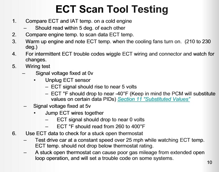
If you want to make absolutely sure that your 5V regulators are still healthy, you can always check other 5V sensors. Or, if your engine uses a drive-by-wire throttle, you can go to the APP sensor (the gas pedal) and check all pins available. At least two of them should have 5V.
Please Log in or Create an account to join the conversation.
- mckenzie
-
Topic Author
- Offline
- New Member
-
- Posts: 15
- Thank you received: 0
I get that externally the 5v can't be shared between pots & thermistors but the diagram shows the 5v is shared internally. What if I have a second 5v ref regulator that is, like the diagram shows, internally feeding both the thermistor & also some other pot sensors.
Basically to me it seems to appear that a 5v reference can indeed be shared between thermistors & potentiometers, so long as its internal & before the current limiting resistor. In this scenario it seems possible that a pot sensor could affect the voltage supplied to a thermistor?
I've only managed to find two other sensors which were camshaft exhaust & camshaft inlet, these are both a good 5v. This engine is bay is super tight!
Sorry, not trying to be smart here or anything!
Please Log in or Create an account to join the conversation.
- Tyler
-
- Offline
- Moderator
-
- Full time HACK since 2012
- Posts: 6126
- Thank you received: 1542
One regulator or the other could be supplying low voltage. BUT, I think this is unlikely because you're not seeing any other fault codes. If the 5V was truly that low, there would be other sensors that would never read correctly. ScannerDanner: "Make sense?" :lol:
The best way to check this would be to find the APP and check both 5V reference wires there. If you have 5V on both, I'd say you're in the clear.
Please Log in or Create an account to join the conversation.
- mckenzie
-
Topic Author
- Offline
- New Member
-
- Posts: 15
- Thank you received: 0
I will have look at the APP like you advise.
Thanks again for the great help here
Please Log in or Create an account to join the conversation.
- Tyler
-
- Offline
- Moderator
-
- Full time HACK since 2012
- Posts: 6126
- Thank you received: 1542
Hall effects would definitely notice, and probably wouldn't work at all.
Let me know what you find at the APP!
Please Log in or Create an account to join the conversation.
- mckenzie
-
Topic Author
- Offline
- New Member
-
- Posts: 15
- Thank you received: 0
5V
9.2V
6mV
4.7V
4mV
10.7V
So this does appear to show 2 separate 5V reference feeds like you explained. I take it's designed like this as a failsafe so if one reference or sensor fails then the other carry's on, or perhaps they both work together for a more accurate reading to the ECU (i.e. both signal voltages should always add up to 5V if they are wired opposite) ?
In conclusion then, both my 5v reference circuits are good & the problem exclusively lies with the ECU output reference for the ECT sensor, with it reading bad at 3.3V ?
Regards
Please Log in or Create an account to join the conversation.
- Andy.MacFadyen
-
- Offline
- Moderator
-
- Posts: 3357
- Thank you received: 1037
A couple of pounds spent on ebay might save replacing the computer.
" We're trying to plug a hole in the universe, what are you doing ?. "
(Walter Bishop Fringe TV show)
Please Log in or Create an account to join the conversation.