A place to discuss hardware/software and diagnostic procedures
Ford's Fuel Pump Monitor Circuit
- Charles Acosta
-
 Topic Author
- Offline
- Senior Member
-

Less
More
- Posts: 79
- Thank you received: 13
7 years 3 weeks ago #27595
by Charles Acosta
Ford's Fuel Pump Monitor Circuit was created by Charles Acosta
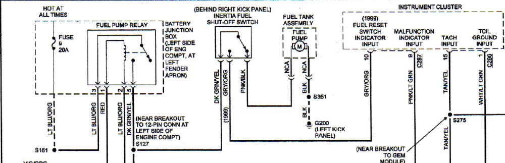
Hello guys its been awhile. I had some time on my hands so I wanted to dig a little deeper into the FP monitor circuit on my truck. I'll provide pictures so you can follow along and they were questions I was asking myself along the way. Here is the diagram and you'll see a relay contact #5 and a splice after it on the DK GRN/YEL wire. One goes to the Inertia switch and the other goes to the ECM labeled FP Monitor. The ECM uses this to check the integrity of the circuit through the FP motor and ground.
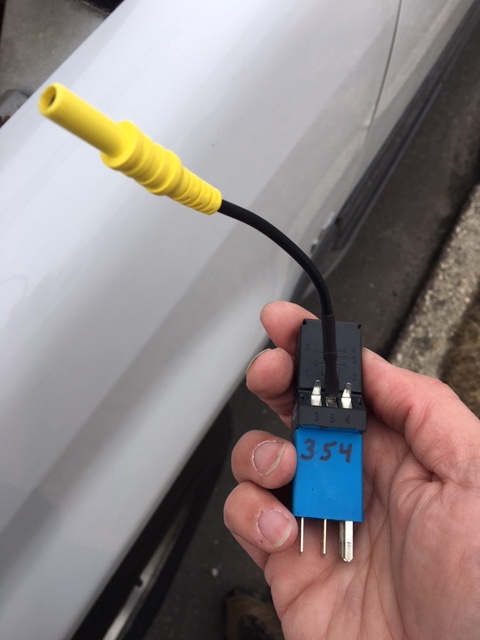
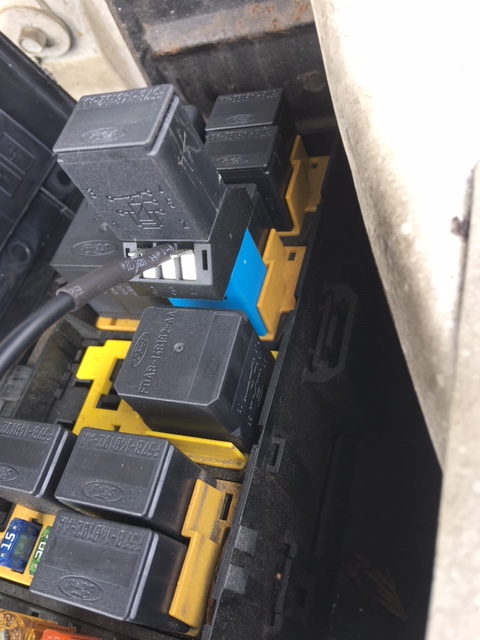
I have a relay jumper with the FP relay connected to it and a jumper to the #5 test port.

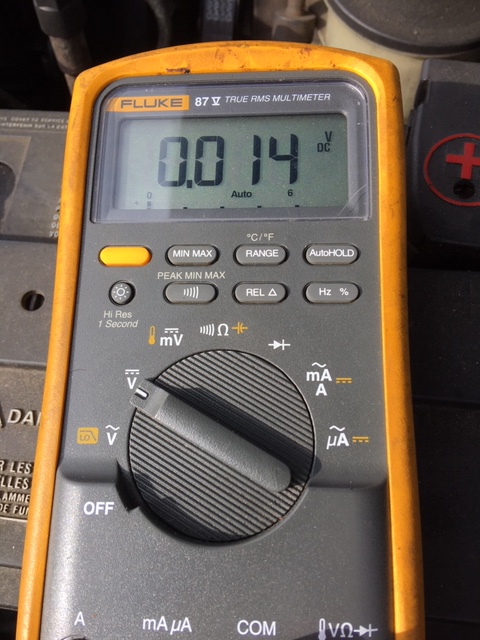
The meter is connected to the relay jumper and the key is on engine off and it reads 14mv. Correct me if I'm wrong, there is a resistor in the ECM in play here and if the circuit is intact low voltage is what it wants to see.
Here is the voltage reading after tripping the inertia switch. The contacts switched diverting voltage to the Fuel Reset indicator in the IP. At this point it set a code FP Secondary Circuit High
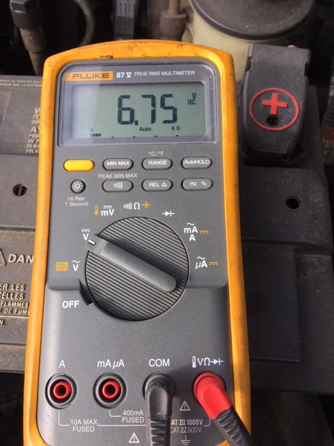
Now I'm asking myself is the 6.75 volts a result of my reading between the resister and the Fuel Reset bulb? Most likely. Next step is to disconnect the inertia switch from the FP simulating an open and expect to see 12 volts To my surprise I saw this....
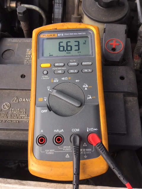
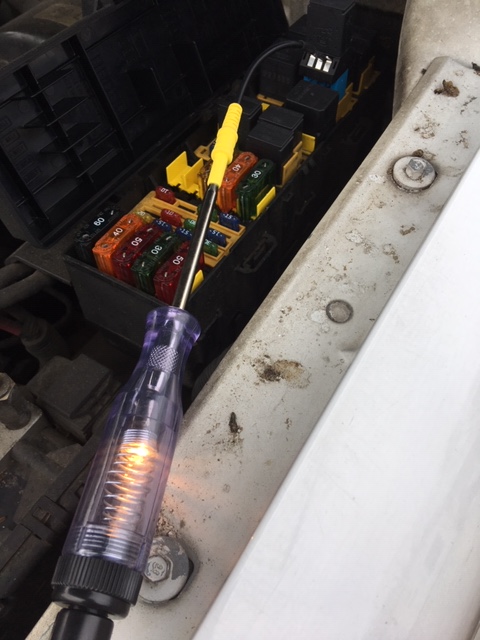
That took me for a loop. I connected my test light to positive to check the circuit integrity through the FP and my test light lit indicating all is good.
Maybe some can explain to me circuit open is 6.6 volts not 12 volts. Circuit design? And a 14 mv reading when a circuit is intact is considered bias voltage? I wonder how many years Ford uses the FP monitor circuit after 1999?
At least i learned a couple of things and the only way to find out is to experiment.
I have a relay jumper with the FP relay connected to it and a jumper to the #5 test port.
The meter is connected to the relay jumper and the key is on engine off and it reads 14mv. Correct me if I'm wrong, there is a resistor in the ECM in play here and if the circuit is intact low voltage is what it wants to see.
Here is the voltage reading after tripping the inertia switch. The contacts switched diverting voltage to the Fuel Reset indicator in the IP. At this point it set a code FP Secondary Circuit High
Now I'm asking myself is the 6.75 volts a result of my reading between the resister and the Fuel Reset bulb? Most likely. Next step is to disconnect the inertia switch from the FP simulating an open and expect to see 12 volts To my surprise I saw this....
That took me for a loop. I connected my test light to positive to check the circuit integrity through the FP and my test light lit indicating all is good.
Maybe some can explain to me circuit open is 6.6 volts not 12 volts. Circuit design? And a 14 mv reading when a circuit is intact is considered bias voltage? I wonder how many years Ford uses the FP monitor circuit after 1999?
At least i learned a couple of things and the only way to find out is to experiment.
The following user(s) said Thank You: Noah, Dylan
Please Log in or Create an account to join the conversation.
- Andy.MacFadyen
-

- Offline
- Moderator
-

Less
More
- Posts: 3357
- Thank you received: 1037
7 years 3 weeks ago #27607
by Andy.MacFadyen
" We're trying to plug a hole in the universe, what are you doing ?. "
(Walter Bishop Fringe TV show)
Replied by Andy.MacFadyen on topic Ford's Fuel Pump Monitor Circuit
A really good subject to bring up which deserves a full exploration but I don't have Broadband Internet this morning so this won't be a full answer.
Yes it is a bias voltage, internal to the engine computer the fuel pump monitor line is supplied with battery voltage which passes through a high value resistor ( thousands of ohms) before it reaches the outside of the engine computer. The internal resistor inside the engine computer is roughly equal to the resistance of the inertia switch LED warning light. This why your meter shows roughly 1/2 battery voltage with the inertia switch tripped.
By reading the voltage at this point the engine computer can work out if there is a supply circuit failure (for example fuse or relay) or a short to ground or the inertia switch has tripped .
A way to make sense of this is to work out or test what voltage shows on the FP monitoring wire in normal running and when all the possible fault conditions occur and note these down to make a table. The fancy name for this is a Truth Table.
" We're trying to plug a hole in the universe, what are you doing ?. "
(Walter Bishop Fringe TV show)
The following user(s) said Thank You: Noah, Charles Acosta
Please Log in or Create an account to join the conversation.
Time to create page: 0.262 seconds