A place to discuss hardware/software and diagnostic procedures
3 Wire MAF question for 23 VW Tiguan

2 weeks 1 day ago #65541
by nhubb
3 Wire MAF question for 23 VW Tiguan was created by nhubb
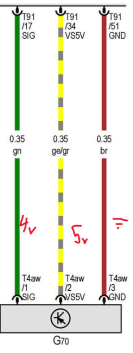
When measuring voltage from the connector with MAF unplugged, I get 5v on the power, and 4v on the signal. this is a working MAF I'm just trying to figure out how this 3 wire works. My question is would this be considered a pull up since I read 4v on the signal and not 0? How does it work from a diagnostic standpoint? Does the computer measure the variation in voltage from that 4v signal wire (if it changes to 3v, 2v, etc.) with car running? I've attached the OEM wiring diagram for the MAF. Thanks in advance!
Please Log in or Create an account to join the conversation.
2 weeks 5 hours ago #65548
by Tyler
Replied by Tyler on topic 3 Wire MAF question for 23 VW Tiguan
That's a good question.
 I couldn't find anything in service info that really gave me a clear answer about sensor operation or normal signal range. I did find some vague references to failure threshold values in the attached chart for P0100, P0101, P0102 and P0103 fault codes:
It may be that this engine controller simply doesn't use a typical bias voltage on the MAF signal line? You could check the MAP sensor as a quick comparison. It may also be that this MAF is actually a frequency generator and doesn't produce a linear voltage signal. You'd need to backprobe the sensor with the engine running and check for changing frequency. Or, check the engine controller data with a scan tool for any MAF PIDs available.
It may be that this engine controller simply doesn't use a typical bias voltage on the MAF signal line? You could check the MAP sensor as a quick comparison. It may also be that this MAF is actually a frequency generator and doesn't produce a linear voltage signal. You'd need to backprobe the sensor with the engine running and check for changing frequency. Or, check the engine controller data with a scan tool for any MAF PIDs available.
Please Log in or Create an account to join the conversation.
1 week 6 days ago #65553
by nhubb
Replied by nhubb on topic 3 Wire MAF question for 23 VW Tiguan
Interesting, thank you for the detailed response! So you think it's possible they use a 4v bias voltage to check circuit integrity on the signal wire?
I'm also assuming by frequency generator that the data would be a square wave correct? Thanks again!
I'm also assuming by frequency generator that the data would be a square wave correct? Thanks again!
Please Log in or Create an account to join the conversation.
1 week 6 days ago #65554
by Tyler
It's possible? I haven't checked the MAF sensor signal bias on any of the newer VW's I've looked at, so it's tough to say with confidence. Again, checking other sensors (like the MAP) may be worthwhile.
Yep, square wave. The raw sensor signal would be measured in Hertz. Again, not sure why that'd matter to the bias voltage on the signal wire, just speculation!
Replied by Tyler on topic 3 Wire MAF question for 23 VW Tiguan
So you think it's possible they use a 4v bias voltage to check circuit integrity on the signal wire?
It's possible? I haven't checked the MAF sensor signal bias on any of the newer VW's I've looked at, so it's tough to say with confidence. Again, checking other sensors (like the MAP) may be worthwhile.
I'm also assuming by frequency generator that the data would be a square wave correct? Thanks again!
Yep, square wave. The raw sensor signal would be measured in Hertz. Again, not sure why that'd matter to the bias voltage on the signal wire, just speculation!
Please Log in or Create an account to join the conversation.
1 week 6 days ago #65555
by nhubb
Replied by nhubb on topic 3 Wire MAF question for 23 VW Tiguan
I'll have to check the MAP sensor when I get the chance to see what the similarities/differences may be.
Theoretically if all assumptions are correct, how would that look? Would the 4v on the signal wire fluctuate as it's being pulled to ground (more or less voltage drop depending on how much current is being used to keep the hot wire at proper parameter)? I'm assuming the PCM wouldn't be monitoring the 5v power feed other than to check if it's operating. I know this is all theoretical at this point just trying to grasp the basics.
Theoretically if all assumptions are correct, how would that look? Would the 4v on the signal wire fluctuate as it's being pulled to ground (more or less voltage drop depending on how much current is being used to keep the hot wire at proper parameter)? I'm assuming the PCM wouldn't be monitoring the 5v power feed other than to check if it's operating. I know this is all theoretical at this point just trying to grasp the basics.
Please Log in or Create an account to join the conversation.
1 week 6 days ago - 1 week 6 days ago #65556
by nhubb
Replied by nhubb on topic 3 Wire MAF question for 23 VW Tiguan
After measuring the voltage on the MAP sensor with the connector disconnected and connected, I found that there is a constant 5v (I'm guessing power) a ground, and two other wires. One has 4.7v-ish and the other had 5ish-v. When connected these drop to 1.1 and .8v or somewhere thereabout at idle. Without back probing the MAF (because I didn't want to break the plastic cover on the back of the connector which covers the wires) I would assume the 4ish-v on the signal wire behaves the same as the above two on the MAP while the 5v would remain constant.
Would this mean that the 5v is reference voltage while the others would be considered bias voltage? How would this work from a sensor standpoint like the MAF, would it likely produce a square wave on the signal wire as the bias voltage is pulled from 0-4v for example?
Would this mean that the 5v is reference voltage while the others would be considered bias voltage? How would this work from a sensor standpoint like the MAF, would it likely produce a square wave on the signal wire as the bias voltage is pulled from 0-4v for example?
Last edit: 1 week 6 days ago by nhubb.
Please Log in or Create an account to join the conversation.
Time to create page: 0.315 seconds