(Solved) 2018 Mazda CX-5: no crank, no start
- Posts: 39
- Thank you received: 7
Please Log in or Create an account to join the conversation.
- Posts: 39
- Thank you received: 7
Please Log in or Create an account to join the conversation.

RJMARRA wrote: Did you try checking the MAF for 5V ref with it unplugged? Not sure on that model if it needs to be unplugged our not. Maybe even confirm 5v ref by checking it on the TPS?
I checked the connecter while it's disconnected. The power does go to the throttle body because I can hear it buzzing/calibrating. Sometimes it sounds like it's staying on for too long.
Please Log in or Create an account to join the conversation.
RJMARRA wrote: also check your grounds at odb2 connector. Diagram attached.
Will do, thanks!
Please Log in or Create an account to join the conversation.
- Posts: 39
- Thank you received: 7
Please Log in or Create an account to join the conversation.
Will do.RJMARRA wrote: i would still verify 5v on another sensor, then start checking pcm pins
Would you happen to have the pinout or wiring diagram of the entire PCM? I just wanted to see which pins are positive and which are ground.
I found this but it's for, I believe, 2014-2016. The 2018 model has two connectors too, but the pins are different.
www.mcx5.org/pcm_inspection-1287.html
Please Log in or Create an account to join the conversation.
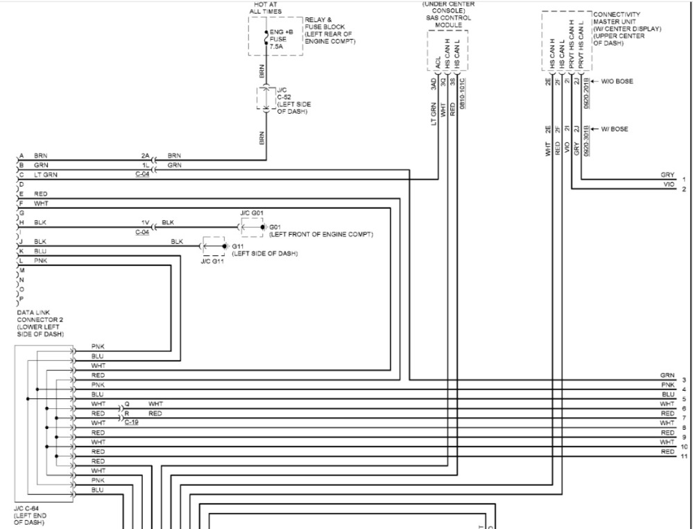
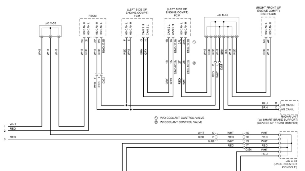
Network Data lines:
Engine Management:
"Knowledge is a weapon. Arm yourself, well, before going to do battle."
"Understanding a question is half an answer."
I have learned more by being wrong, than I have by being right.
")
Please Log in or Create an account to join the conversation.
vallis wrote: Most of the work done is body-related; nothing mechanical or electrical. I removed the belt because it was on my way as I needed to bend the radiator support bracket back in place. I carefully inspected all the wires and connectors including ground, everything is in place.
Page 3 top right of the network diagram Chad posted. Some of that wiring is probably in the collision damaged area you were working.....
I'd check voltage to ground on DLC pins 6 and 14 KOEO. May as well check 3 and 11 too since you couldn't talk to the MS-CAN either.
Please Log in or Create an account to join the conversation.
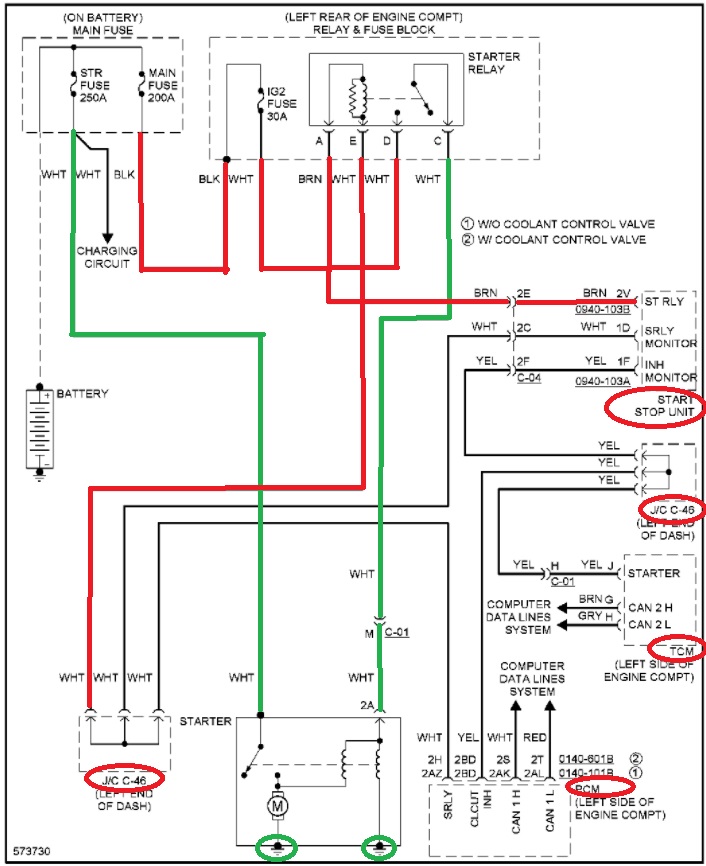
Chad wrote: Starting Diagram:
Network Data lines:
Engine Management:
Thank you!!
Please Log in or Create an account to join the conversation.
Matt T wrote:
vallis wrote: Most of the work done is body-related; nothing mechanical or electrical. I removed the belt because it was on my way as I needed to bend the radiator support bracket back in place. I carefully inspected all the wires and connectors including ground, everything is in place.
Page 3 top right of the network diagram Chad posted. Some of that wiring is probably in the collision damaged area you were working.....
I'd check voltage to ground on DLC pins 6 and 14 KOEO. May as well check 3 and 11 too since you couldn't talk to the MS-CAN either.
Will do, thank you!
Please Log in or Create an account to join the conversation.
1. If the PCM is not dead, how come I can't access it through regular OBD code reader?
2. I noticed a strange behavior from the throttle body. It is buzzing constantly when the ignition is on (see the video). I timed it and it buzzed for at least 10 minutes and did not sound like it was going to stop. I don't know if this is contributing to the no crank issue but I thought I'd mention it. It reminded me of the Mercedes video that Paul did when the cooling fan was blowing at full speed.
3. I did not back probe the sensors, I just unplugged the connector and measured the voltage directly. Do I need to?
4. I did not get a chance to start diagnosing the CAN. I have a general idea about the network but is there something in particular I need to focus on?
I went back and checked all the wires in the impacted area (front right). I redid all wire looms after I inspected everything. There are still a couple of wires that I need to shield; other than that, nothing is broken there from what I have seen.
Link to both images and video: imgur.com/a/pIGubeJ
Thank you all!
Please Log in or Create an account to join the conversation.
- Posts: 39
- Thank you received: 7
If I were you I would start by taking voltage measurements at the relay on all pins. maybe you can narrow it down to one wire and and that will point us in a closer direction.
Probably wouldn't hurt to double check the 3 fuses listed in this diagram too. I know you have already checked them but in case you missed one or somehow one has blown since you last checked them by accident through one of your other tests.
Let us know.
Please Log in or Create an account to join the conversation.
- PIN 16 reads 12.5v and good ground at PINs 4 and 5.
- Resistance at CAN high and low measures 60 (with battery disconnected). I disconnected the computer and resistance read 120.
- Voltage to ground of PIN 6 and 5: 2.56v and 2.35v. I forgot to check PINs 3 and 11, I will later.
Please Log in or Create an account to join the conversation.
RJMARRA wrote: I have attached a diagram of your starting system. I have traced in green the "known good circuit" because you said you jumped the relay meaning the output side should be ok. I've made some red traces where your problem could lie, as well as circled some components in red which apparently all "talk" on the input side of the circuit.
If I were you I would start by taking voltage measurements at the relay on all pins. maybe you can narrow it down to one wire and and that will point us in a closer direction.
Probably wouldn't hurt to double check the 3 fuses listed in this diagram too. I know you have already checked them but in case you missed one or somehow one has blown since you last checked them by accident through one of your other tests.
Let us know.
Thank you very much for that!! I was just looking at the diagram that Chad shared. I will take measurements and post back.
BTW, I just posted the CAN readings. Can I safely assume the network is good?
Please Log in or Create an account to join the conversation.
vallis wrote: Can I safely assume the network is good?
Network wiring appears to be OK but you haven't ruled out a network problem. There is probably something wrong with your Forscan set up or the vehicle network. Only reason I say probably is I'm not sure how Forscan will react if it can't read the VIN from the PCM.
Please Log in or Create an account to join the conversation.
Matt T wrote:
vallis wrote: Can I safely assume the network is good?
Network wiring appears to be OK but you haven't ruled out a network problem. There is probably something wrong with your Forscan set up or the vehicle network. Only reason I say probably is I'm not sure how Forscan will react if it can't read the VIN from the PCM.
The software does connect to the ELM327 adapter, I wonder if it is defective. I get "Connection to adapter has been established" with a green check mark, followed by an in-line and a pop-up error saying "Unable to connect to the vehicle. Please make sure the ignition key is ON and try again".
I will go over the set-up again, continue to try, and will let you know if I get anything.
Please Log in or Create an account to join the conversation.
Edit: The service manual shows its location (see attachment).
Please Log in or Create an account to join the conversation.
vallis wrote: The software does connect to the ELM327 adapter, I wonder if it is defective. I get "Connection to adapter has been established" with a green check mark, followed by an in-line and a pop-up error saying "Unable to connect to the vehicle. Please make sure the ignition key is ON and try again".
Did a little digging. It appears V.2 Forscan needs to grab the VIN from the PCM before it'll communicate with any other modules. And there doesn't appear to be any way to manually enter the VIN.
You could try uninstalling V.2 and installing V.1 to see if it finds anything.
forscan.org/forum/viewtopic.php?t=4324
forscan.org/forum/viewtopic.php?f=5&t=1690
Please Log in or Create an account to join the conversation.
- Posts: 39
- Thank you received: 7
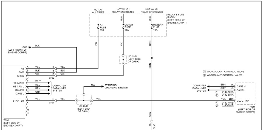
( A ) +B : Battery Voltage at all times
( B ) GND: 0v or ground at all times
( C ) IG SW: Battery voltage with the key on
Can you confirm all 3 of those volatges?
Please Log in or Create an account to join the conversation.
- There is constant power from the main starter fuse at the positive battery terminal to the starter.
- If I understood the diagram correctly, the Start Stop Unit sends power to Pin A of the starter relay, and the PCM grounds Pin E. I checked both pins with the test light by attaching one end to the + and the other to Pin E, but it did not light up. So this must mean there is no ground at the Pin. I did it the other way around for Pin A, no power when I push the start button.
With the ignition on, I supplied ground to Pin E and power to A, respectively, and it only cranked (I used a test light for Pin E as a ground medium to avoid cooking the PCM in case something goes wrong).
Does the power have to come directly from the Push button unit? Would it make a difference if I supplied power at the push button?
Any thoughts?
Please Log in or Create an account to join the conversation.