Issue with seeing secondary ignition signal

Please Log in or Create an account to join the conversation.
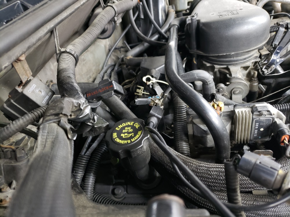
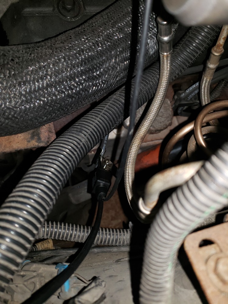
Can you include some pictures of your connections and scope setup?
"Knowledge is a weapon. Arm yourself, well, before going to do battle."
"Understanding a question is half an answer."
I have learned more by being wrong, than I have by being right.
")
Please Log in or Create an account to join the conversation.
Please Log in or Create an account to join the conversation.
Please Log in or Create an account to join the conversation.
Please Log in or Create an account to join the conversation.
- juergen.scholl
-

- Offline
- Platinum Member
-

- Active partschanger
- Posts: 1194
- Thank you received: 446
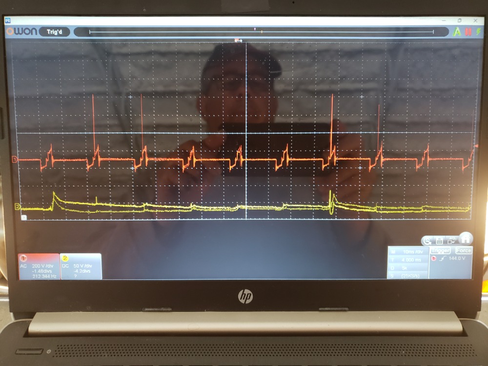
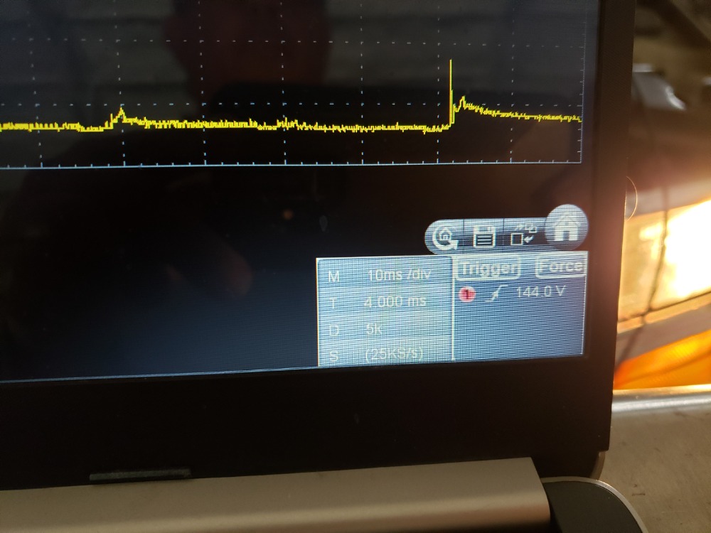
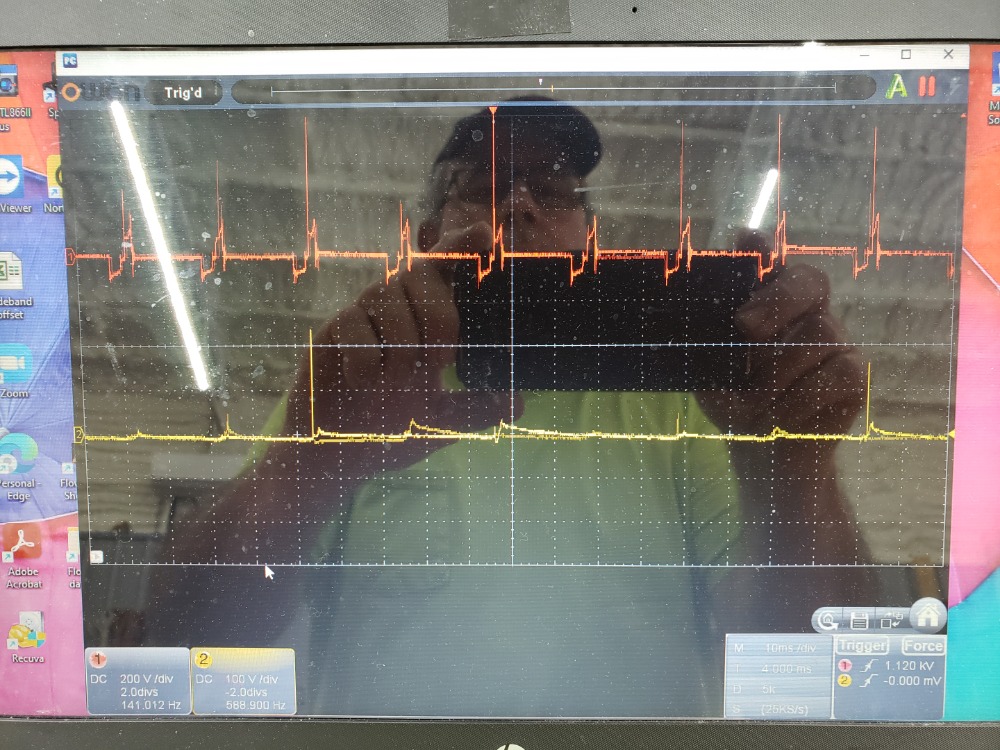
To me it looks like a (too) low sample rate...Not sure how the sample rate is calculated on this scope, it says 25 ksamples per second. Your overall screentime seems to be 200ms (20 divisions x 10ms each). If there's only one AD converter for both channels this might actually come down to as low as 2500 samples per channel per screen. Another contributing factor maybe the memory/buffer size though probably it is well above 5000 memory points which could be the required size for this configuration.
An expert is someone who knows each time more on each time less, until he finally knows absolutely everything about absolutely nothing.
Please Log in or Create an account to join the conversation.
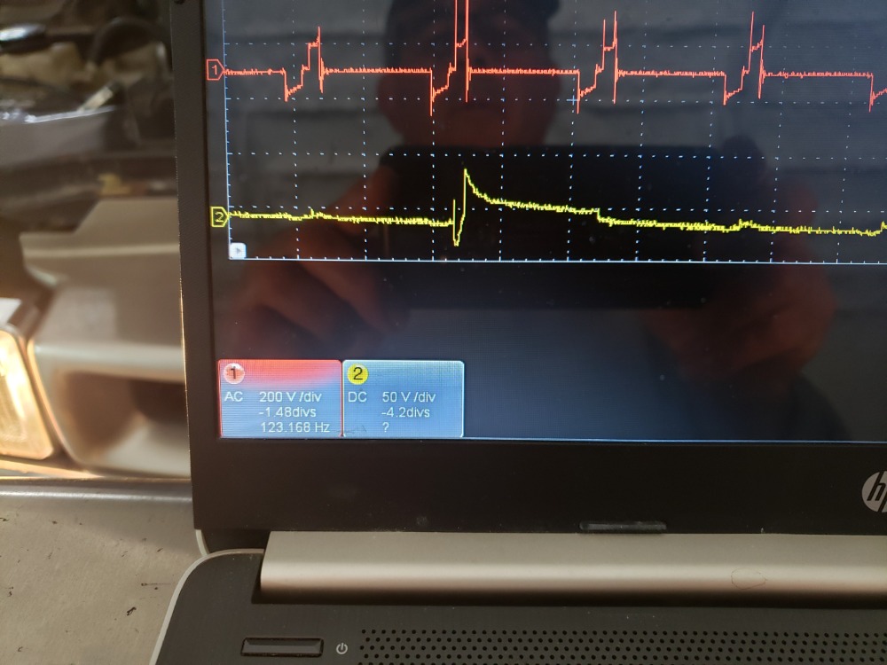
Channel 1 is ac-coupled, why?
Forgot to change #1 channel back to DC.
To me it looks like a (too) low sample rate...Not sure how the sample rate is calculated on this scope, it says 25 ksamples per second. Your overall screentime seems to be 200ms (20 divisions x 10ms each). If there's only one AD converter for both channels this might actually come down to as low as 2500 samples per channel per screen. Another contributing factor maybe the memory/buffer size though probably it is well above 5000 memory points which could be the required size for this configuration.
The specs for the oscope says that the sample rate can be as high as 100MS/s but I'm not sure how to change it, more research.
Please Log in or Create an account to join the conversation.
- juergen.scholl
-
- Offline
- Platinum Member
-
- Active partschanger
- Posts: 1194
- Thank you received: 446
The specs for the scope says that the sample rate can be as high as 100MS/s but I'm not sure how to change it, more research.
This is where understanding of specs come in and scope manufacturers do a lot to keep it cryptic...
The real time sample rate mainly depends on sweep time, memory depths and screen resolution. The cited "up to" sample rate spec is based on the fastest time base/sweep time but does not hold up when the on screen time is increased.
You scope does show a sample rate per second value. You'll notice that this value will decrease when you increase the time base/sweep time. This is basically how you control the sample: more screen time = less sample rate and vice versa. Put maximum sample points (buffer size) into the mix and you get close to the real abilities and limitations of a given scope.
An expert is someone who knows each time more on each time less, until he finally knows absolutely everything about absolutely nothing.
Please Log in or Create an account to join the conversation.
The specs for the oscope says that the sample rate can be as high as 100MS/s but I'm not sure how to change it, more research.
The 'scope has a 5kS buffer and you've got 200 milliseconds on the screen. The software has set the sampling rate, to 25kS/s, to match the timebase. And that ain't near fast enough to get a good ignition parade or a reliable trigger with a secondary pickup. You'll have to knock the time down and look at each cylinder individually to get sufficient detail. Then you might be able to get a reliable secondary trigger too. Personally I couldn't with the Hacktek. I use a rpm pickup that came with an automotive DMM to trigger on ignition secondary. Can differentiate between the ignition event and noise from other cylinders, and waste sparks, with it.
Please Log in or Create an account to join the conversation.
Please Log in or Create an account to join the conversation.
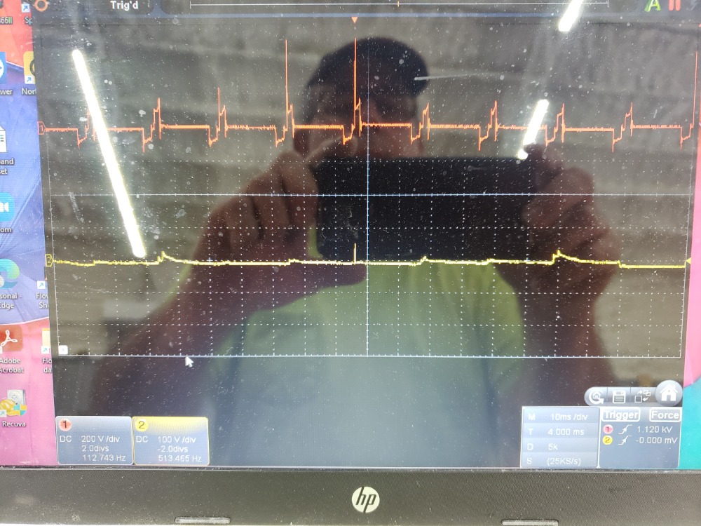
why does the waveform look so good for the probe connected to the coil wire channel #1 and not so good for the one connected to the #1 plug wire on channel #2. This holds true even when I have the time/div at 1ms as opposed to 200ms. Is it because the waveform is just weaker at the plug?
For lack of a better explanation, yes. The farther away from the coil, the longer the plug wire, the more resistance...Now, add in the extra air gap that you are jumping in the distributor cap and rotor, an amount of energy has been lost. It is, usually, recommended to connect your secondary leads as close to the coil as possible.
If you want to see what is, truly, happening inside the coil, connect your labscope to the control side of the coil, set your scope to a 400v scale, capture a primary voltage waveform, and couple it with a coil current ramp.
"Knowledge is a weapon. Arm yourself, well, before going to do battle."
"Understanding a question is half an answer."
I have learned more by being wrong, than I have by being right.
Please Log in or Create an account to join the conversation.
Not an answer to your scope questions, but I'm fairly familiar with these trucks. The most common issues are CMP retard, fuel delivery (either upgrading the stock CSFI spider to MFI, or fuel pump) and vacuum leaks. I would first check your CMP retard with your scanner, it should be 0 degrees (+/-2 degrees). It is common for the distributor gear to become worn. It is not adjustable without either modifying the hold down bracket to give you some play or buying an after market distributor that has a hold down that gives you ability to adjust retard.
Thanks for trying to help. I have owned several S10's so know all about what you are talking about. This one has been kicking my butt. I have set the CMP to zero and replaced the complete distributor, cap, rotor, wires and plugs with new. Smoked the engine for vacuum leaks, none found. Replaced injectors with new balanced 36lb injectors because I want to put a tailpipe turbo on it when I fix this issue. I have HPtuners so I have tried changing the tune to try to help but with all of these changes, nothing has fixed the issue. Hense getting a Oscope to look at the crank/cam sensors and try to see if my missfire is ignition or fuel.
Please Log in or Create an account to join the conversation.
Please Log in or Create an account to join the conversation.
- juergen.scholl
-
- Offline
- Platinum Member
-
- Active partschanger
- Posts: 1194
- Thank you received: 446
I got some what of a triggered wave form on the #1 plug wire. But can someone tell me why when I have the coil wire probe clamped to CH1 and CH2 probe clamped to the #1 plug wire at the plug or where ever it seams to make no difference? The wave form on the #1 plug wire looks like it is seeing every firing of each cylinder. Shouldn't that probe on the plug wire only see that fire cycle and not the other 5 cylinders. I would think I should see an ing wave form for that cylinder only when the dist rotor passes by that contact in the distributor. I would like to use the #1 cylinder ing wave form to idenify which is #1 in the wave that is connected to the coil wire since its wave form is so much better. Hopefully someone can help me with this.
You got an image or file to share? What is your sync pickup like? Does this happen as well when triggering from a different cylinder?
An expert is someone who knows each time more on each time less, until he finally knows absolutely everything about absolutely nothing.
Please Log in or Create an account to join the conversation.
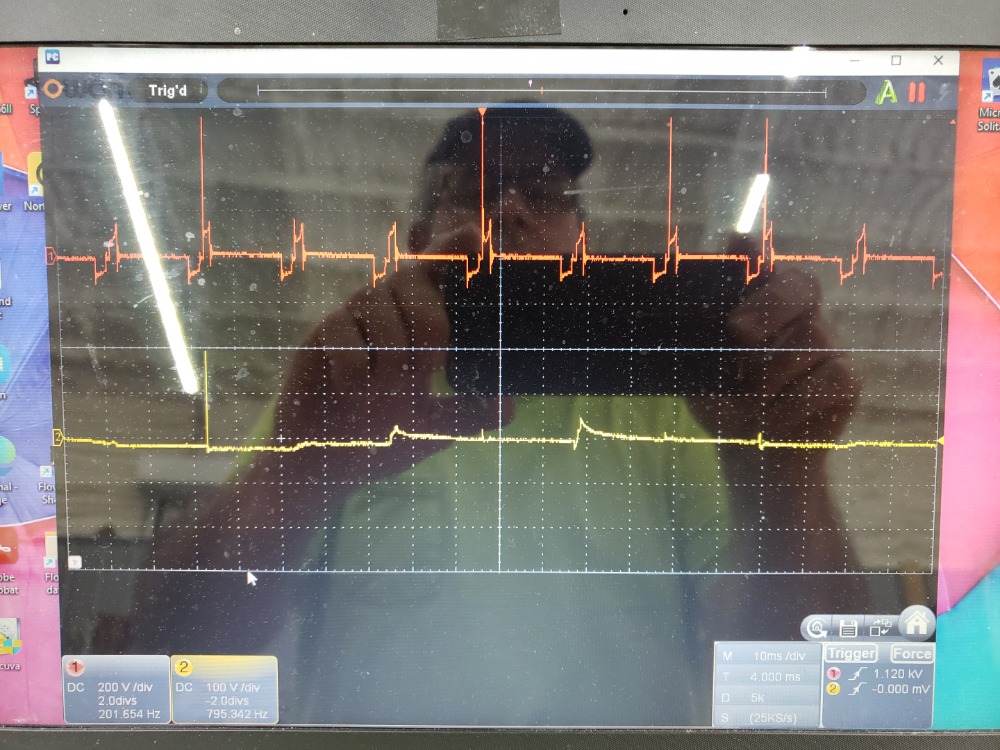
can someone tell me why when I have the coil wire probe clamped to CH1 and CH2 probe clamped to the #1 plug wire at the plug or where ever it seams to make no difference? The wave form on the #1 plug wire looks like it is seeing every firing of each cylinder. Shouldn't that probe on the plug wire only see that fire cycle and not the other 5 cylinders.
Secondary ignition is VERY high voltage, up to 40,000 volts. Due to this you can see Secondary Ignition patterns/interference in, almost any wire, or circuit, that you test in the engine compartment. When you are NOT testing Secondary, you will learn to ignore these "bleed-over" patterns. To minimize the interference, try to keep your scope, test-leads, and probes as far away from Ignition coils and plug wires, as possible.
Since you ARE testing Secondary, you must realize that you will see the Ignition pattern of the plug wire that you are on AND you will/may see the interference/bleed-over patterns of the other cylinders.
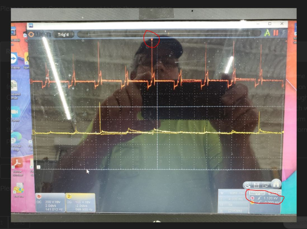
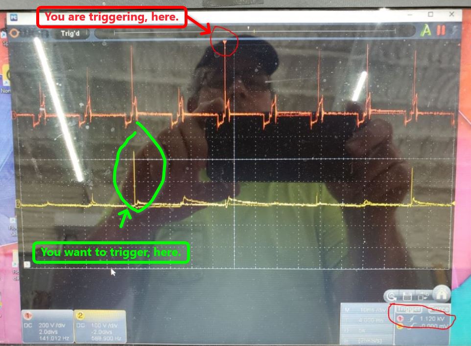
So, the question is how to determine which Ignition event is the event that your probe is on.
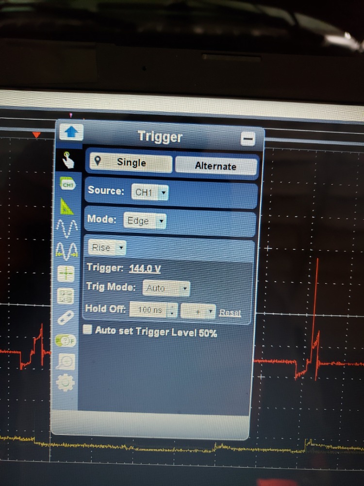
The Ignition event that your probe is testing will, usually, be stronger and the "interference" events will be a bit weaker. Try raising your trigger level so that you only trigger on the strongest Ignition event.
"Knowledge is a weapon. Arm yourself, well, before going to do battle."
"Understanding a question is half an answer."
I have learned more by being wrong, than I have by being right.
Please Log in or Create an account to join the conversation.
Please Log in or Create an account to join the conversation.
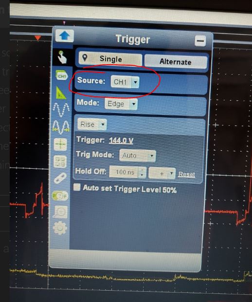
If you want to trigger of Cylinder #1, which is connected to Channel #2, then you need to set your trigger to Channel #2.
"Knowledge is a weapon. Arm yourself, well, before going to do battle."
"Understanding a question is half an answer."
I have learned more by being wrong, than I have by being right.
Please Log in or Create an account to join the conversation.
Please Log in or Create an account to join the conversation.