Home made in cylinder transducer
- Posts: 4417
- Thank you received: 959
"Ground cannot be checked with a 10mm socket"
Please Log in or Create an account to join the conversation.
- Posts: 4417
- Thank you received: 959
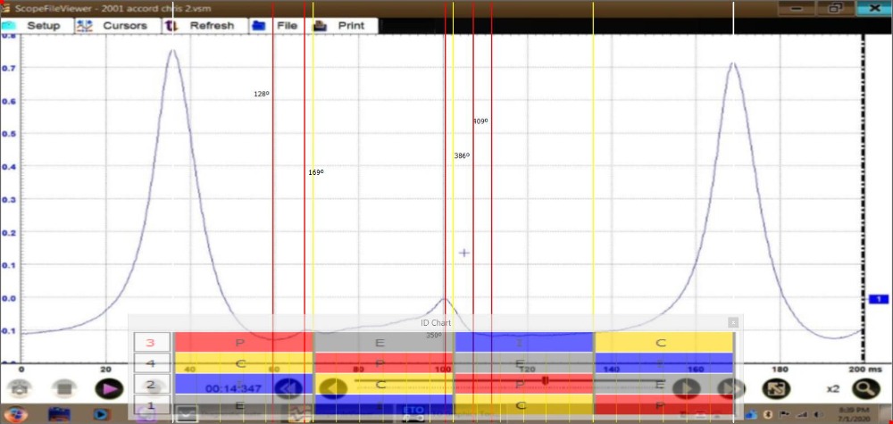
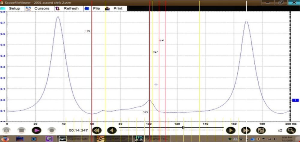
The second thing is the exhaust event.
It looks like it takes longer for the exhaust valve to open than on the Taurus, but that could be a normal difference between the two cars I suppose.
The pressure builds and kind of ramps up at the end of the exhaust stroke but the duration seems roughly the same as that of the Taurus known good capture. Then the cylinder goes into an unequal vacuum compared to what was in the cylinder at the end of the expansion stroke making for uneven pockets.
I wanted to get a known good from cylinder 1 or 4 of the Accord that's broke for an apples to apples comparison, but it won't run on one cylinder, lol.
Any of the experts care to reflect on the waveform and share there their interpretation of what that actually means is happening in the cylinder?
"Ground cannot be checked with a 10mm socket"
Please Log in or Create an account to join the conversation.

Noah wrote: Any of the experts care to reflect on the waveform and share there their interpretation of what that actually means is happening in the cylinder?
I'm no exspurt by any means but it looks like positive pressure building on the exhaust stroke. I checked to confirm 2 & 3 are both TDC at the same time so I suspect that exhaust stroke pressure build is the adjacent cylinders compression leaking across a blown head gasket.
Please Log in or Create an account to join the conversation.
- juergen.scholl
-

- Offline
- Platinum Member
-

- Active partschanger
- Posts: 1195
- Thank you received: 446
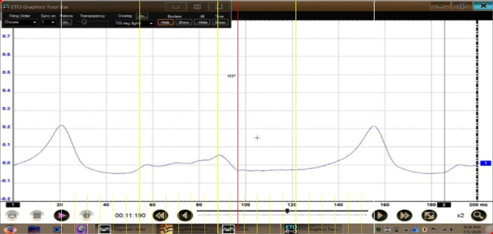
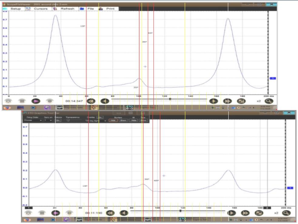
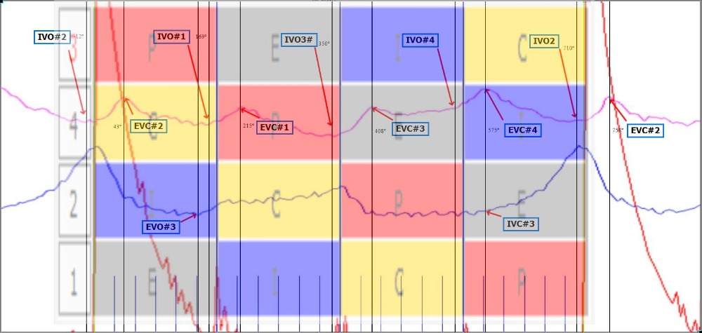
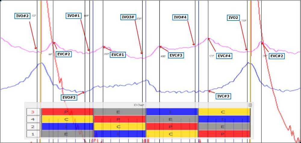
Cyl #4 got a massive leak, somewhere;compression towers are shifted. some valve events on #4 seem to take place later than on #3. Both cylinders can not evacuate the exhaust gas properly. The pressure build up in #4 both on the exhaust ramp as on the compression stroke does show a very rounded curve....
It looks to me that the exhaust is partially clogged, affecting both cylinders. Furthermore the #4 intake valve does not close properly.
I attached some pictures with rulers...

An expert is someone who knows each time more on each time less, until he finally knows absolutely everything about absolutely nothing.
Please Log in or Create an account to join the conversation.
Please Log in or Create an account to join the conversation.
- Posts: 4417
- Thank you received: 959
The cylinder with high compression is cylinder#2, the lower compression cylinder is #3.
I attempted to collect a capture from #4 but it won't run on one cylinder.
I get out early today so I'm going to try to make a sensor to put on the intake unless something else comes up.
Thanks for the feedback guys!
"Ground cannot be checked with a 10mm socket"
Please Log in or Create an account to join the conversation.
- Posts: 4417
- Thank you received: 959
It's very helpful for me to have your insight.
I agree with your assessment of the exhaust not being able to leave the cylinder quickly.
The fact that it takes a long time for the exhaust to reach atmospheric coupled with the fact that both cylinders look similar in that regard makes me wonder if the DIY timing belt replacement could have installed another problem after he broke the car beating on it.
Do you think that the exhaust pressure displayed could be accounted for by incorrect cam timing, considering it is common to both cylinders, or is there something else in the capture that might indicate this is not the case?
Just so we're all on the same page this is a single over head camshaft design.
Using AC coupling puts atmosphere @ 0.03v. I am roughly at sea level.
The actual running compression of the known good Taurus was about 75psi according to my mechanical gauge.
Just to give an idea of the voltage to pressure scale.
"Ground cannot be checked with a 10mm socket"
Please Log in or Create an account to join the conversation.
- Posts: 4417
- Thank you received: 959
"Ground cannot be checked with a 10mm socket"
Please Log in or Create an account to join the conversation.
- juergen.scholl
-
- Offline
- Platinum Member
-
- Active partschanger
- Posts: 1195
- Thank you received: 446
Noah wrote: When I get back Monday I will rename the captures accordingly. I also have the .vsm files if anyone would like to view them in Shop stream.
Please upload the vsm files. Thank you.
An expert is someone who knows each time more on each time less, until he finally knows absolutely everything about absolutely nothing.
Please Log in or Create an account to join the conversation.
- Posts: 4417
- Thank you received: 959
I tried a GM fuel tank pressure sensor, but wasn't immediately impressed. I ended up with a GM MAP sensor, so its an absolute pressure sensor, high voltage is BARO, low voltage is vacuum.
The first capture is engine cranking closed throttle, relative compression & intake vacuum. There is no appreciable in cylinder waveform during cranking so ch1 was turned off for this capture.
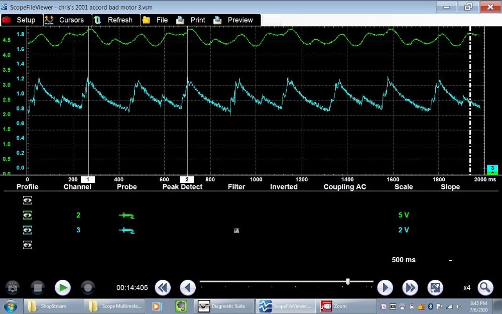
Next up is a running capture featuring intake manifold vacuum, in cylinder compression on cylinder #3 and ignition sync #3
"Ground cannot be checked with a 10mm socket"
Please Log in or Create an account to join the conversation.
- Posts: 4417
- Thank you received: 959
"Ground cannot be checked with a 10mm socket"
Please Log in or Create an account to join the conversation.
- juergen.scholl
-
- Offline
- Platinum Member
-
- Active partschanger
- Posts: 1195
- Thank you received: 446
I'd love to see a a cranking exhaust pressure waveform, maybe you can take one?. Although the two bad cylinders are adjacent it does not look to me as if a blown headgasket causes one cylinder to evacuate into the other; in this case I'd expect both cylinders to be afffected in a more similar way....
You may want to try to AC- couple the MAP sensor in order to gain a higher resolution.
An expert is someone who knows each time more on each time less, until he finally knows absolutely everything about absolutely nothing.
Please Log in or Create an account to join the conversation.
- Posts: 4417
- Thank you received: 959
")
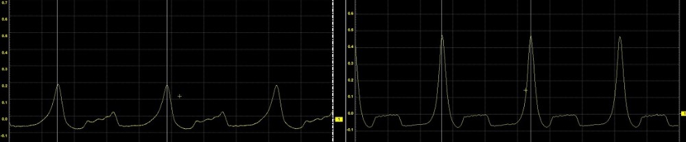
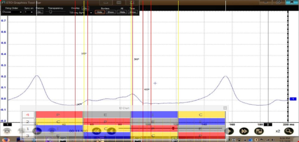
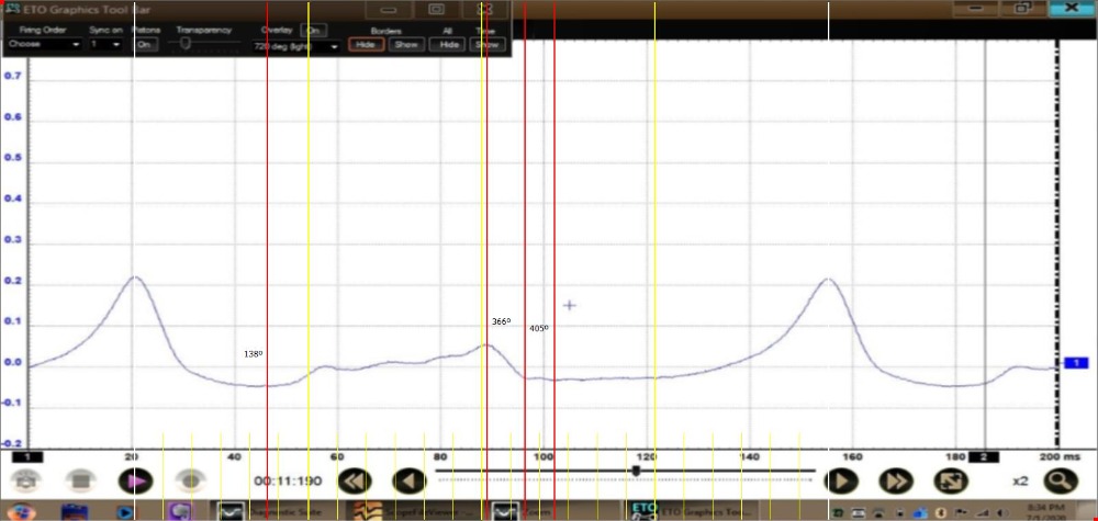
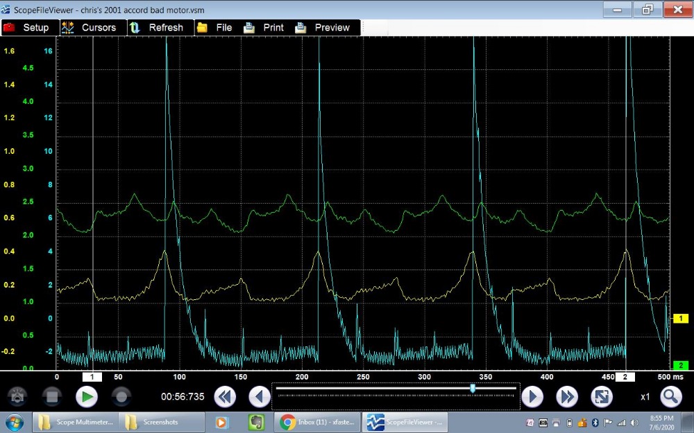
With the vacuum sensor AC coupled it behaves differently.
Instead of outputting a linear voltage, the waveform looks more like a differential sensor. If I have the opportunity after work to play some more I will attempt to gather some exhaust patterns.
Again, thank you for taking the time to look at my captures and share your knowledge.
This kind of testing is new to me, but I would very much like to understand it enough to start incorporating it into my routine.
"Ground cannot be checked with a 10mm socket"
Please Log in or Create an account to join the conversation.
- Posts: 4417
- Thank you received: 959
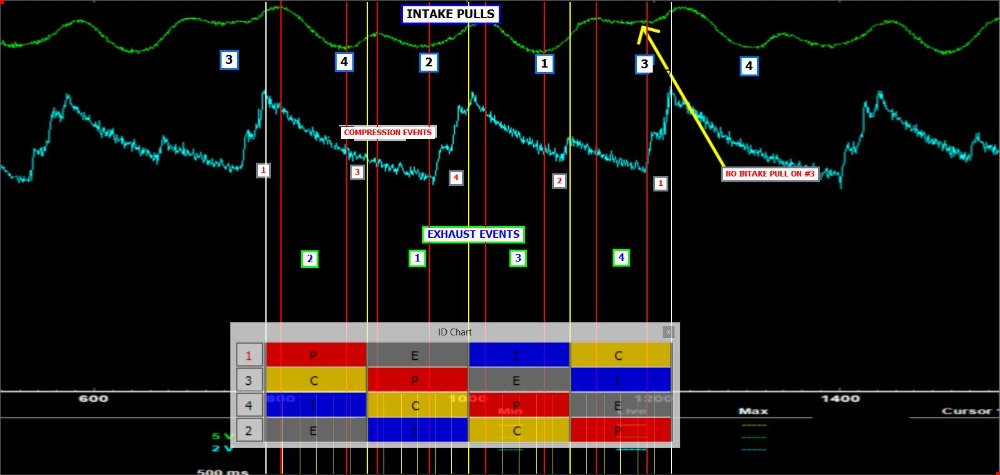
Nice job picking out the firing order on the relative compression & vacuum wave form.
I really should have used an ignition sync.
I honestly expected to see a greater compression hump from cylinder #2 based on the in cylinder pattern from #2.
It looked pretty regular while running compared to the couple of known good captures I have from the Taurus and my Ridgeline. Could the use AC coupling be skewing the captures?
Of course running compression is lower than cranking, so that must be the reason for it but for me it was unexpected. (I was secretly beginning to doubt the previous techs cranking compression test results after seeing the in cylinder for the first time)
Another thing that I was thinking about was the low compression on cylinder 3 coupled with the lack of an intake pull for the same cylinder. Is it possible that the intake valve does not open, resulting in no air to compress ultimately resulting in no compression? I know you said that cylinder 3 has a massive leak, is that based mostly on the low compression towers or is there another indicator that I am not seeing?
Once again, I greatly appreciate your help in understanding the results of these tests.
It will be fun to make a hypothesis and then prove or disprove it before the car is junked.
"Ground cannot be checked with a 10mm socket"
Please Log in or Create an account to join the conversation.
- juergen.scholl
-
- Offline
- Platinum Member
-
- Active partschanger
- Posts: 1195
- Thank you received: 446
any news on that one? Did you dissect it?
An expert is someone who knows each time more on each time less, until he finally knows absolutely everything about absolutely nothing.
Please Log in or Create an account to join the conversation.
- Posts: 4417
- Thank you received: 959
) to hopefully better grasp the anatomy of the waveform.Did the .vss files work for you? I was looking at one last night that I took at higher rpm and it looked like the pressure on the exhaust stroke was equal to the pressure on the compression stroke after returning to near idle speed.
I think I've gotten as far as I can without actually observing the fault. Hopefully tomorrow afternoon I will have the time and ambition to pull it out of the junk yard and do a leak down test and maybe pull the head.
Thank you for your help and interest Juergen. You are a genuine asset to this community.
"Ground cannot be checked with a 10mm socket"
Please Log in or Create an account to join the conversation.
Noah wrote: Could the use AC coupling be skewing the captures?
It doesn't seem to be giving a consistent atmospheric pressure reference, which is making it impossible to tell whether the exhaust stroke is slowly rising to atmospheric or building positive pressure. You mentioned earlier that AC coupling puts atmospheric around 0V but the latest #3 in cylinder picture never drops to zero and appears to be peaking north of 0.2V at the end of the exhaust stroke?? I think it'd be worth getting a DC running compression before you tear into it.
I also agree with Juergen that exhaust back pressure would be good to have. There's probably something turbocharged in the yard you can harvest a suitable sensor from
")
Please Log in or Create an account to join the conversation.
- Posts: 4417
- Thank you received: 959
I'm pretty sure the Snap On transducer and the one I am using are both 500psi.
I think I have 2 secondary rpm pick-ups collecting dust, I may try to cannibalize one....
I definitely need to do more testing to be able to translate the voltage scales to actually pressure and vacuum.
I will continue post here as I experiment, thank you for your input. It is greatly appreciated!
"Ground cannot be checked with a 10mm socket"
Please Log in or Create an account to join the conversation.
Also if the aux 0V floats there's a good chance the USBs will too. Something else to bear in mind if you're unable to get a consistent DC reading at atmospheric pressure. I wouldn't tie the 'scopes 0V to 'scope ground but powering the transducer with a wall wart and tying it's 0V to the 'scope ground shouldn't cause any problems. Or at least not any expensive ones :lol:
www.scannerdanner.com/forum/diagnostic-t...sure-transducer.html
Please Log in or Create an account to join the conversation.
- Posts: 4417
- Thank you received: 959
Thank you once again Matt, owe you a beer
I found the utility in Windows to test various functions of the scope, including the 5v power supply on the aux plug and was able to ID power and ground. I intend to re-pin the Snap-On rpm pick up too utilize it to power the transducer.
Mine isn't power all the time, so I don't know if it powers on when you select an appropriate test lead preset for a given channel or how it works yet.
I Also want to try a "wall wart" as you call it to see if it skews the 0 line compared to the USB ports on the Verus.
I downloaded the PDF and gave it a glance but I will give it a thorough read through this afternoon.
Once again, thank you very much!
"Ground cannot be checked with a 10mm socket"
Please Log in or Create an account to join the conversation.