Want to know if any interest towards automotive computers and circuit internals
I have been doing board level repairs for a little more than 10 years now. I'm interested in finding out if you guys would like to know more about the circuits or internal side of things for automotive computers. Not so much repairing on a chip level but rather info towards how things are normally handled internally and which common things are shared between the same chips. I have seen a few videos of SD where he complains about the damn engineers not telling us everything esp the internal workings.
Like the shared voltage supply on that crank & cam video where it turned out to be shorted Cam sensor wiring which caused the circuit to be pulled low for both.
I have shared some info in another thread which basically derailed from the original topic and figured maybe I should try and put important and useful parts into a thread here or share some document. The idea would be to give you guys some insight for when you are diagnosing computer related issues. Some of the info may go a bit low level, I mean chip level in order to understand how "chips" react to certain inputs/outputs. But I will try and simplify most where possible.
Now keep in mind... I have had this idea in my head for the past week or so and don't have anything made up or written down and also don't want to just paste a bunch of random links and images. I'd like to make it easy to understand in a neat way. Maybe a series of things to be covered.
I can supply some oldish schematics and circuit layouts and all kinds of datasheets. A great part of the info would be based on the Bosch systems. Esp the EDC15/16/17. I have seen all kinds of ECU's and from that I can tell they all use the same layout or style almost like they copied it or the other way around
 who knows.... Layout meaning the use of chips and the over all flow and placement of parts on the PCB. So this info should be useful on any ECU and not limited to only that one make. I have worked on mechatronic gearbox as well and they are also very interesting and its nearly all the same stuff...
Anyways all of this will require some basic knowledge of electronics in the meantime a good place to start would be www.allaboutcircuits.com/education/
This will all depend on the feedback I get here, before I go and spend time doing this...
Thanks
")
while alive { live(toFullest=true) }
Please Log in or Create an account to join the conversation.
"Knowledge is a weapon. Arm yourself, well, before going to do battle."
"Understanding a question is half an answer."
I have learned more by being wrong, than I have by being right.
")
Please Log in or Create an account to join the conversation.
")
Please Log in or Create an account to join the conversation.
- Matts Auto
-

- Offline
- Premium Member
-

- Posts: 155
- Thank you received: 28
Please Log in or Create an account to join the conversation.
Please Log in or Create an account to join the conversation.
- juergen.scholl
-

- Offline
- Platinum Member
-

- Active partschanger
- Posts: 1197
- Thank you received: 446
An expert is someone who knows each time more on each time less, until he finally knows absolutely everything about absolutely nothing.
Please Log in or Create an account to join the conversation.
Please Log in or Create an account to join the conversation.
- Posts: 4422
- Thank you received: 961
"Ground cannot be checked with a 10mm socket"
Please Log in or Create an account to join the conversation.
Cool. I'm not sure where I should begin though. Maybe we can go through different/random topic's discussing each in some detail before moving to the next?
I don't want to end up explaining things that you guys already know... As well as explaining stuff that need some basics to make sense of.
Sooo... This first post we could handle the crank / cam sensor supply circuit and controller. As I mentioned in the first post and @Tyler mentioned it as well.
Remember this is all based on the ME7.1/5/7 systems. They are bosch(marked) chips and I have seen them in other ECU's as well. The different manufacturers use a lot of Bosch chips along with TLE/Infineon & others. So with that mentioned I'm sure the basics apply to different ECU systems.
I'm not a Electronic Engineer so don't take my word for everything. Go do your own research. And when you find something new come share it
Firstly I can't tell you how exactly that internal system works on that Impala... But I can try and give you some insight on how the common system works on the ME7.1/5/7. @Tyler you should open one of those Impala ECU's if you have one laying around(broken) and trace the Crank&Cam sensor inputs/outputs and take note where they go on the PCB.
Okay before I start with the circuit stuff, here are some info regarding the basics of circuit protection . This is all based on the Arduino which make it easy to understand and to play with because its dirt cheap, this should give you guys an idea of how it works, this is all simple and remember there are many configurations, this is just to give you some insight. Also remember the IC's they use in ECU's do A LOT MORE! The first thing is safety & reliability. So the internal protection functions of IC's used in ECU's are pretty legit.\
To add for those that want to play with circuits, here is a nice Circuit Simulator to play with. www.falstad.com/circuit/circuitjs.html Keep in mind that Simulators aren't anything like real life.
The following section pretty much handles all the RPM related circuits. In this ME7.1/5/7 system its handled in the CJ910. The same chip takes care of the 5V supply. Everything is pretty much self explained.
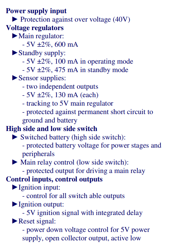
Here a snip from the CJ911 see the Sensor supply info's. Permanent Short to Ground Protection, That's just the chip itself. We can go into detail later about the different states/flags that chips set when they find something is bad/good.
At the Bosch website you can view all the different systems/IC's. They actually give you some good info on what is what. That way you can get a idea of what sensors/actuators run off the same IC's. pdf on Bosch products
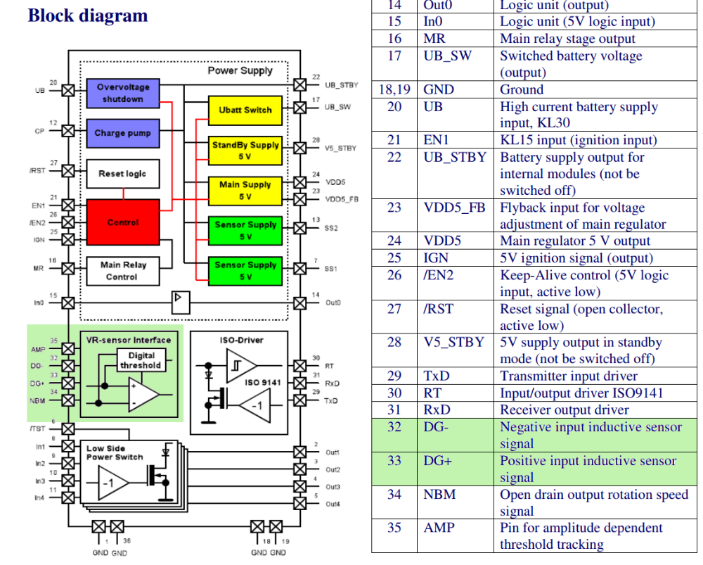
Here is a snip about the CJ910 the CJ911 is pretty much the exact same thing.

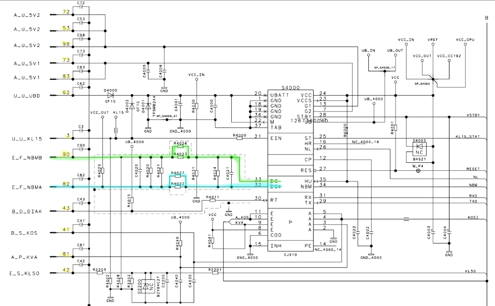
Here is a snip from a Schematic regarding the System Basis IC. CJ910/911
And here is a snip from the Datasheet regarding the CJ910/11.
A nice old flyer with some info on different sensors and some sensor details just for some extra info/reading.
And here is a copy paste from a 6A H-bridge driver. It's a CJ220. What I want to show is the functional Description. In it you can get a idea of how the IC can protect it self.
The outputs are protected against short circuit to VB,
GND and over the load. Whenever at least the supply
voltages (VB) is below its specific threshold, the power
stages are switched in tristate and the status flag is
switched low.
If the supply voltage is over the specific threshold again,
the power stage switches independently into normal
operation, according to the input pins, and the status
flag is reset.
In case of over-temperature or over-current is detected
the power stages are switched in tristate independent of
the input signals and the status-flag is switched low.
If the level changes from high to low on DI or low to high
on EN, the output stage switches on again, if the
temperature is below the specified limit. The status-flag
is reset to high-level.
The maximum current which can flow under normal
operating conditions is limited to Imax = 6,5A ±20%.
When the maximum current value is reached, the output
stages are switched tristate for a fixed time. According
to the time-constant the current decreases exponentially
until the next switch-on occurs.
Quote has nothing to do with the CJ910/11 but still worth a mention for those that don't know that the IC's have build in protection for some variable situations. Depending on the IC's importance those functions will either be more advance or simple.
I did't say much in this post... Linked and pasted more images than anything else... But I'm sure we will get the ball rolling from here on.
Let me know what works and what doesn't. Ask questions about specific things if needed and I'll try and answer or find something that explains it. Otherwise we will just have to figure it out between us.
while alive { live(toFullest=true) }
Please Log in or Create an account to join the conversation.
I'm probably not asking this correctly so please be patient.
Please Log in or Create an account to join the conversation.
Uhm I think I get what you are asking... How the High Side and Low Side switches work and or what they are for?
Either way I'll give it a shot. The way I understand it...
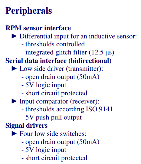
Looking at the snip/image from the CJ911 datasheet: (Also I added the peripherals snip...)
1. Its protected. self explained
High side:
1. It gives power to the power stages and peripherals. Basically handles the Power(supply) for the ECU(its onboard chips) and other power outputs to the peripherals listed in the added image. (which i forgot about in the first post sorry...)
So yes that would be Battery Voltage and your 5V. In some cases I have seen them taking it down to 3.3V as well for internal components(chips).
High side is usually for switching your power rails on/off.
Low side:
1. Main relay Control. self explained ground switch for relay control see: Ground side vs Power side (High/Low) switching
Take that into mind; considering a "No Main Relay control" or anything else this chip handles, when having done the rest of the checks... Like you are sure the ECU is at fault. It can then be something as simple as that part of the chip... OR 1 broken/blown/shorted/over-heating complete chip either way if you had to repair it you would replace the whole chip(1piece) and if needed any supporting components esp caps.
The Block diagram shows the different sections inside the chip(well what's released to public).
Here are some quick searches/bookmarks. Some basics/advance and examples explaining low-high side drivers. These are just drivers by them self...
Just for those that questioned it...

Mosfets and Transistors(BJT) may sometimes look the same outside... but they aren't inside! Here they are explained
Some basics explained around low-high side Mosfet drivers
Transistors
Aaand more talk on Mosfet drivers
Hopefully that helps?
Goodluck
while alive { live(toFullest=true) }
Please Log in or Create an account to join the conversation.
Please Log in or Create an account to join the conversation.
As usual, I have questions!
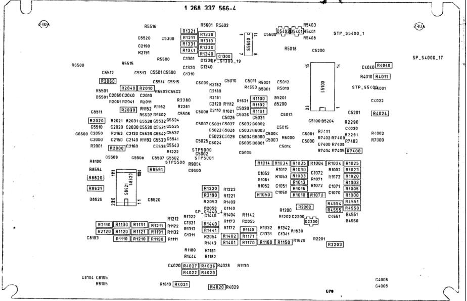
The schematic from the system basics of the CJ1910 specifically got my attention. I've (badly) marked it up in Paint for clarification.
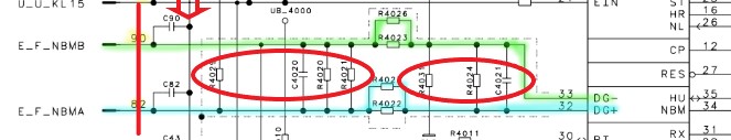
First, is it correct to say that everything left of the red line is outside the physical module? And everthing to the right is inside?
Second, as I understand it, this circuit is a variable reluctance sensor reporting to the CJ1910 so it can power some kind of main relay. Basically, a crank sensor input so the fuel pump gets turned on? If that's so, what's with all the resistors and connectors (circled) between the positive and negative? :huh: I understand you're not the engineer, so any speculation you have would be appreciated.
Third, what's the purpose of C90, C82, and its circuit (arrow)? It would appear that all pins are connected to this common 'bus'. Or, am I reading the diagram incorrectly? :silly:
Please Log in or Create an account to join the conversation.
Tyler:
Well you sure didn't disappoint, sir! :woohoo: Makes me feel like I'm back in school.
 Nice!, you seem to like the low level stuff.
Questions & Answers:
1. Yes.First, is it correct to say that everything left of the red line is outside the physical module? And everything to the right is inside?
2.Second, as I understand it, this circuit is a variable reluctance sensor reporting to the CJ1910 so it can power some kind of main relay. Basically, a crank sensor input so the fuel pump gets turned on? If that's so, what's with all the resistors and connectors (circled) between the positive and negative? :huh: I understand you're not the engineer, so any speculation you have would be appreciated.
2.1 Yes as far as I understand it. Its the circuit for the RPM sensor; Being Inductive Type.
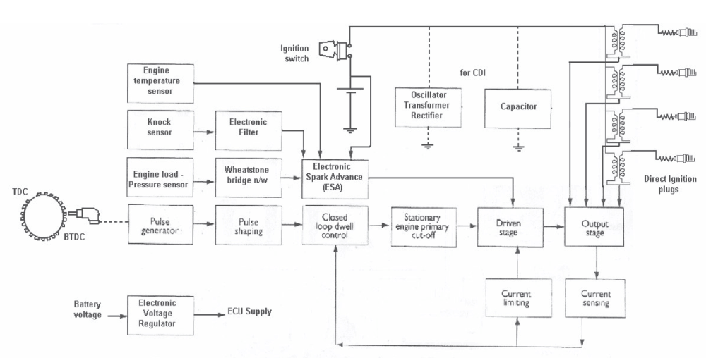
2.2 Well looking from a high point yes... But its a lot more complex than that or not so much complex but rather important for a good RPM signal. From this ECU_Design_pdf see the following Flow Chart & Block Diagram.
The first one kinda goes in hand with what you suggested.
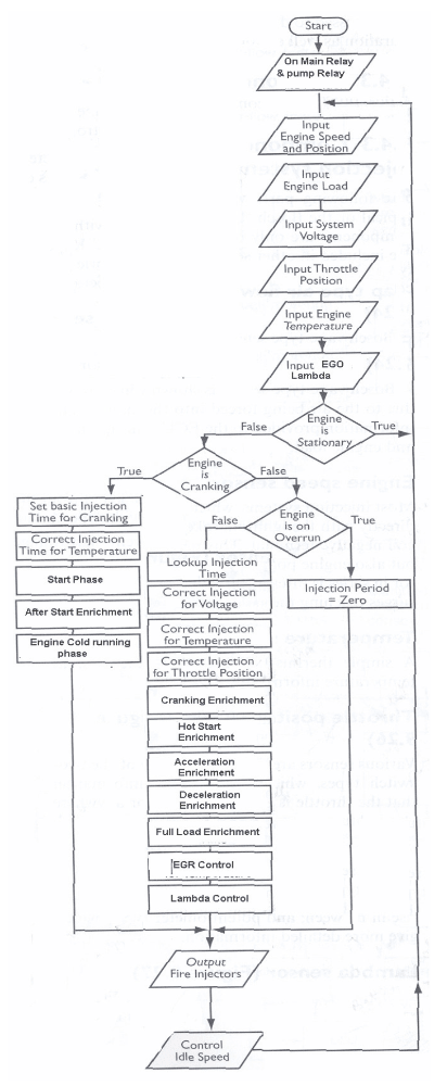
The second shows how import that input is.
2.3 Yeah I'm no EE... I would think various support. Protection, Filter, Stabilizing, Correction.. I dono. I'm sure it has to do with the good waveform's (bottom page) you get when you scope them(depending on the scope & system I guess) also in this case its AC. I'll dig and see what I can find about this...
3.Third, what's the purpose of C90, C82, and its circuit (arrow)? It would appear that all pins are connected to this common 'bus'. Or, am I reading the diagram incorrectly?
- Same as above I guess. Protection, Stabilizing, Filtering, Response...
- Arrow tip is GND MB.
hope that answers some stuff.
while alive { live(toFullest=true) }
Please Log in or Create an account to join the conversation.
 More questions as I read and digest this stuff.
The Block diagram shows the different sections inside the chip(well what's released to public).
This was something that I thought of while going over the diagrams and datasheets you posted. Obviously, the parts manufacturer wants to sell their product, but doesn't want to divulge (too much) how exactly they make the magic happen. Have you run into situations where you were left wanting for information because it wasn't provided by the manufacturer?
Second, I'm still digging deeper into this CJ1910 chip. Do you find that this type of 'job delegation' is common across different brands of ECU's? As in, is there usually one chip (like the CJ1910) that handles 5V/crank sensor input/main relay operation, or do different OEM's break up the jobs differently? Are there other common layouts that you've seen?
Please Log in or Create an account to join the conversation.
- juergen.scholl
-
- Offline
- Platinum Member
-
- Active partschanger
- Posts: 1197
- Thank you received: 446
An expert is someone who knows each time more on each time less, until he finally knows absolutely everything about absolutely nothing.
Please Log in or Create an account to join the conversation.
This was something that I thought of while going over the diagrams and datasheets you posted. Obviously, the parts manufacturer wants to sell their product, but doesn't want to divulge (too much) how exactly they make the magic happen. Have you run into situations where you were left wanting for information because it wasn't provided by the manufacturer?
Indeed. Esp with automotive electronic IC's... But I have to say having spent so much time in repairing more common equipment like laptops/desktops/automated systems(feeders, conveyor belt controllers...) and all the rest of the stuff... I got to understand the concept of how they usually put these things together. Like the CJ910 or CJ911 pretty much reminds me of the BQ24767 chips that handle charging along with the EC that controls the States(starting the rest of the power rails), the TPS51125 (and the rest) that handle the 5V & 3.3V. SPI/I2C and all the other busses. All the things mentioned are just some random selected ones that fit the above discussed IC(CJ910/11) there are allllot more things not mentioned here... There are so much! but having a general understanding of how it all works helps with not knowing the "insides" (datasheet stuff) of the particular IC's because you can kinda fill in the blanks with the other info. At the end of the day its all pretty much the same sh*t.
Second, I'm still digging deeper into this CJ1910 chip. Do you find that this type of 'job delegation' is common across different brands of ECU's? As in, is there usually one chip (like the CJ1910) that handles 5V/crank sensor input/main relay operation, or do different OEM's break up the jobs differently? Are there other common layouts that you've seen?
I guess you meant CJ910 | CJ911 they are both the same, just different models.
They seem to do the same... Like with pretty much everything else they always do the same thing, some may have some tiny different tweaks here and there but the fundamental thing stays exactly the same. Some chips on Laptop MB's, I found are easily interchangeable like you can swap a different make with another make in some cases. The overall circuit setup/layout is very similar as well ecus -> laptops/desktops/controllers; different power rails, signals... The external / extra support components like external Transistors/Mosfets and Passive parts are sometimes the exact same this is between different ecu makes as well. I found the main difference also pretty obvious is the MCU(Microcontroller) on ECU's, esp between different makes. Along with its supporting Memory well not so much the memory chip but the ROM internal/external(BIM/Image/Firmware/BIOS all the same basically like computers on chip level).
Looking at the Infineon Products you'll see how many things they have that does the same as the bosch ones. And the bosch CJ910/CJ911 we have been discussing is actually very old... Infineon has this TLE8080 under Engine Management IC's that's pretty much the same thing. (Have reached the limit on links... so find it from the Product List)
But some have more some have less... You'll see that the Infineon System Basis IC's ones offer some similar options but lacking some so they have Management IC's and Different Power solutions so you could break the "jobs" up if needed to some extend. You always have to think about reliability & safety. If this fails, that happens. Like the crank and cam sensors... Take a look at the video from the link above about one of the System Basis IC's Evaluation Board, will give you some insight on how things can be controlled with software.
So finally it's really down to the micro-controllers. They can run differently and have different programs(BIN, Flash, Firmware...) Programming them enables the use of any common "worker" chip (inputs/outputs) to do things you want it to do. putting it very basic...
Also it depends on the functions the "worker" chip offers but what I'm saying is, they made a bunch of chips that do the basic things and the "Micro controllers" could use those chips in different ways. Hope that makes sense.
A list from Wikipedia (basic over view)
Key elements See the Infineon Diagrams just for another overview.
Core
- Microcontroller
Memory
- SRAM
- EEPROM
- Flash
Inputs
- Supply Voltage
- Digital inputs
- Analog inputs
Outputs
- Relay drivers
- Injector drivers
- Logic outputs
Communication links
- Housing
Take a look at the MCU here for example to get a idea of the "extras"
Hi juergen.scholl, thanks for posting those forgot to add those... There are some links to other things near the end of my other old thread as well...
Hope it all makes sense... I can get off track easily....
while alive { live(toFullest=true) }
Please Log in or Create an account to join the conversation.
") Many thanks!
Many thanks!I feel like there's tons of great information in those data sheets. For instance, I picked out one of their LIN tranceivers - a TLE7259 . I'd always wondered why a LIN network shows battery voltage in its recessive state. All the automotive training I've seen tells you it should be that way, but never why. :silly: But the data sheet spelled it out!
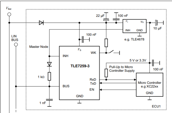
At the master node, the LIN bus is wired directly into B+ across a 1K ohm resistor and diode. Does this matter to my diagnosis? Probably not, but it's still cool.
Please Log in or Create an account to join the conversation.
Tyler wrote: If that's so, what's with all the resistors and connectors (circled) between the positive and negative? :huh: I understand you're not the engineer, so any speculation you have would be appreciated.
Third, what's the purpose of C90, C82, and its circuit (arrow)? It would appear that all pins are connected to this common 'bus'. Or, am I reading the diagram incorrectly? :silly:
So as it turns out, yes, I was reading the diagram incorrectly. :blush: Those aren't connectors, but capacitors. Duh. This makes way more sense, especially as I spend more time reading product diagrams.
The engineers love to throw a bunch of microfarad capacitors in between circuits, because... electrons? :silly:
Please Log in or Create an account to join the conversation.
Sorry were away over x-mas...
Tyler: Yeah they sure love to "cap" everything. (stable, filter ,safety....)
Indeed. Good food for thought.
BTW Happy new year to everyone! while alive { live(toFullest=true) }
Please Log in or Create an account to join the conversation.